4.4.3.1 Technical data of the inputs
ThedigitalinputsarespeciedinaccordancewithIEC61131-2type3.
Status „0“ Status „1“
-3…5V 11…30V
4.4.3.2 Technical data of the outputs
Thedigitaloutputsareshort-circuitproofandspeciedinaccordancewithIEC61131-2.
Max. switching voltage 30V
Max. current
0.7Aperoutput
1 A total current for all outputs
Internal resistance 250Ω
Max. switching frequency 1 kHz
Inductive load withoutfree-wheelingdiodemax.300mJ
Table 17: Technical data of the outputs
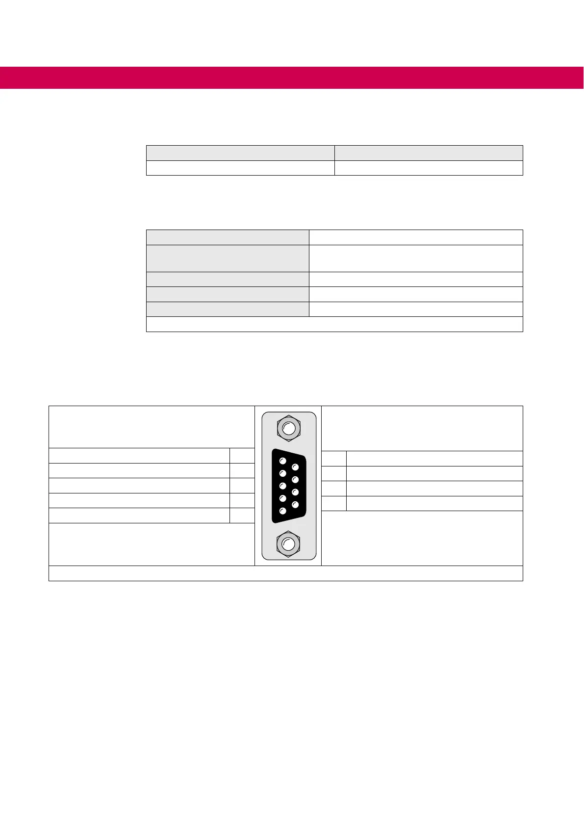
4.4.3.3 Assignment of the interfaces
5 4 3 2 1
9 8 7 6
5 4 3 2 1
9 8 7 6
reserved - do not assign ! 1
6 reserved - do not assign !
TxD (RS232) 2
7 DGND (reference potential)
RxD (RS232) 3
8 TxD-A(RS485)
RxD-A(RS485) 4
9 TxD-B(RS485)
RxD-B(RS485) 5
Figure 34: Assignment of the interfaces
4.4.4 Digital inputs and outputs X2A
Additionally to the central inputs and outputs of the control unit each axis module is
equipped with own inputs and outputs. Terminal block X2A includes four digital inputs
and four digital outputs with the appropriate mass terminals.
60
CONNECTION OF THE CONTROL
 Loading...


