4.4 Connection of the control
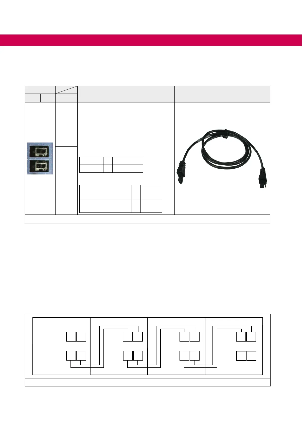
4.4.1 Error chain terminal X2C, X2D
Channel
Description Connecting cable error chain
2 1 Name
X2C
The terminal strips X2C and X2D are in-
ternally parallel connected. Thus, each
terminal strip can be used as input or out-
put.
Based on the power supply unit the error
chain contains two channels and can sup-
ply maximally 64 axis modules.
Status channel 1:
OK = U > 9 V
Error = U < 5 V
Status channel 2:
Release axis
modules
= U < 5 V
no release axis
modules
= U > 9 V
X2D
Figure 32: Error chain terminal X2C, X2D
4.4.1.1 Error chain (channel 1)
Thersterrorchannelisanerrorchain.Ifthereisanerrorinamodule,theothermod-
ulescanbenotiedoftheerrordirectlyviathischannel.Theresponsetotheerrorcan
be parameterized.
4.4.1.2 Error power supply unit (channel 2)
At this error channel the axis modules get the information that the power supply unit is in
errorstatusandthemodulationofallaxismodulesmustbeswitchedo.
4.4.1.3 Wiring example error chain
X2C
1
2
X2D
1
2
X2C
1
2
X2D
1
2
X2C
1
2
X2D
1
2
X2C
1
2
X2D
1
2
Figure 33: Wiring example error chain
58
CONNECTION OF THE CONTROL
 Loading...


