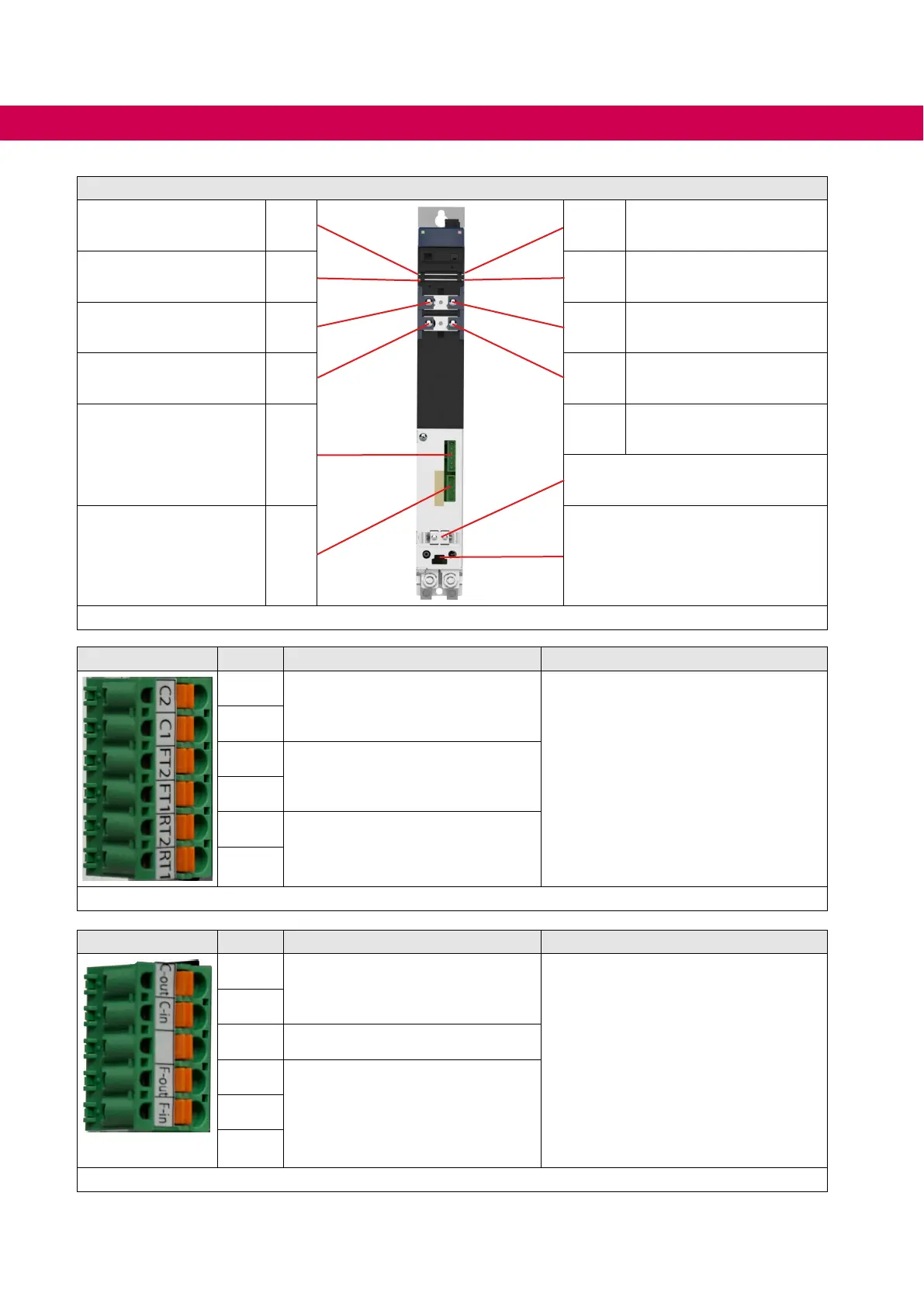
Connections of the front side
+24Vbus X1C.1
X1C.3 +24Vbus
0 V X1C.2 X1C.4 0 V
DCbus+ X1D.1 X1D.3 DCbus+
DC bus- X1D.2 X1D.4 DC bus-
Protection feedback and
temperature switch
X1E
Shield clamps
Contactor and
fan control
X1F Snap-in for front cover
Figure 18: Connections of the front side
X1E Name Function Connection data
C2
Control input
(for checking whether the contactor
has switched)
permissible connection cross section:
0.2…2.5mm²,AWG24-12
Strippinglength:10mm
C1
FT2
Temperature monitoring of the AIC
lter
FT1
RT2
Temperature monitoring of the
braking resistor
RT1
Figure 19: Terminal block X1E
X1F Name Function Connection data
C-out
Control for supply /regenerative
contactor; switches after comple-
tion of the precharging
permissible connection cross sec-
tion:0.2…2.5mm²,AWG24-12
Strippinglength:10mm
max.load:6A/1500VA
max. inductive load:
24 V DC (DC13): 2 A
250VAC(AC15):3A
max. starting current (capacitive load of
the protective circuit):
<2.0Aduringtherelevanttimeof1ms
C-in
– not assigned
F-out
ControlforfansoftheAIClter
F-in
Figure 20: Terminal block X1F
50
INSTALLATION AND CONNECTION
 Loading...


