Voltage measurements
Assuming “BENCH” reset conditions, the basic procedure is as follows:
1. Connect test leads to the INPUT HI and LO terminals. Either the front or rear inputs can
be used; place the INPUTS button in the appropriate position.
2. Select the measurement function by pressing DCV or ACV.
3. The AUTO annunciator indicates that autoranging is enabled. If you want manual rang-
ing, use the RANGE
▲
and
▼
keys to select a measurement range consistent with the
expected voltage.
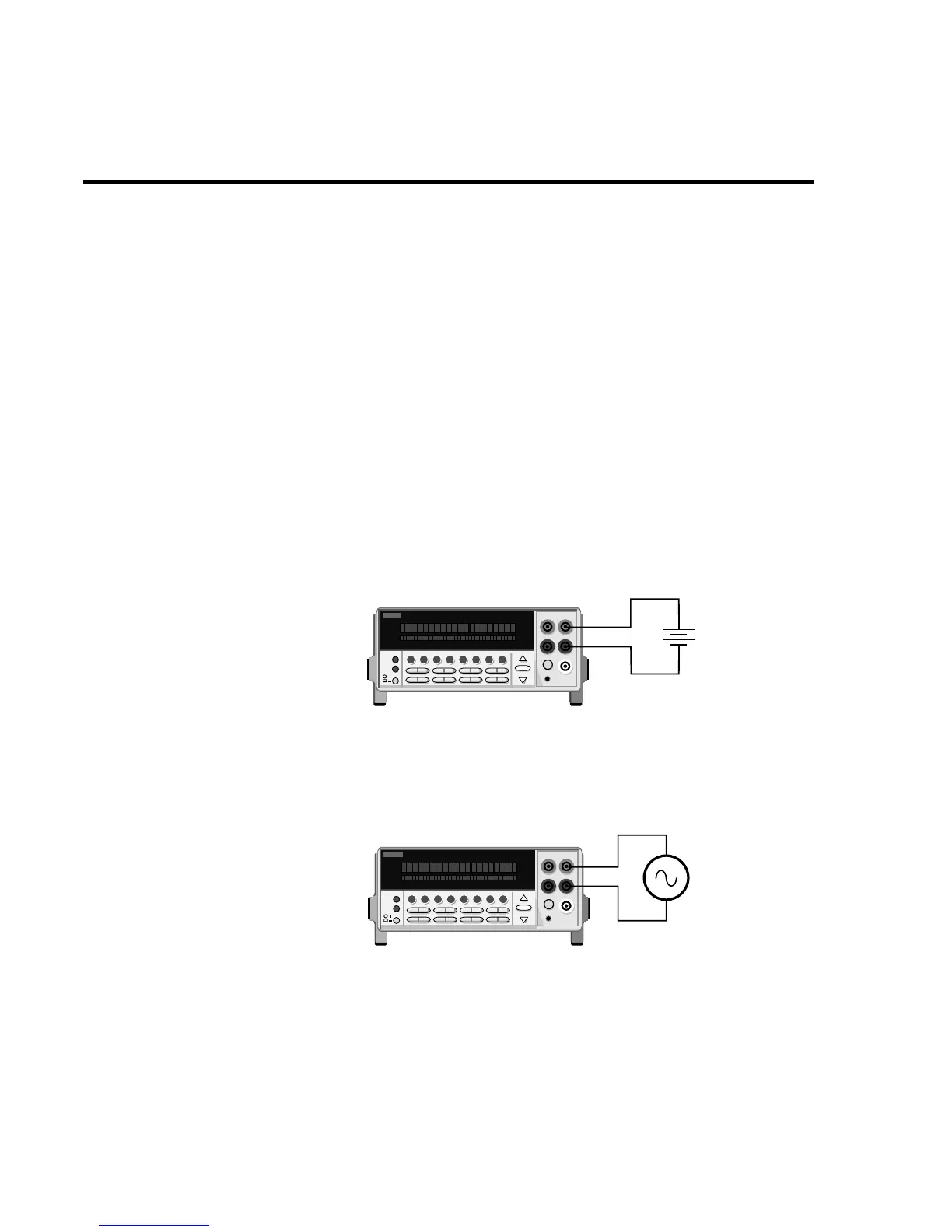
4. Connect test leads to the source as shown in Figure 4.
CAUTION Do not apply more than 1100V peak or 2
×
10
7
V•Hz to the input, or instru-
ment damage may occur.
5. Observe the display. If the “Over o w” message is displayed, select a higher range until
a normal reading is displayed. Use the lowest possible range for the best resolution.
6. Take a reading from the display.
2001 MULTIMETER
1234567891012345678910
EDIT ERR REM TALK LSTN SRQ REAR REL FILT MATH 4W AUTO ARM TRIG SMPL
Caution: Maximum Input = 1100V peak, 2 x 10
7
V•Hz
AC Voltage
Source
Model 2002
Input Impedence = 1MΩ shunted by <140pF
Figure 4
DC and AC
voltage measurements
2001 MULTIMETER
1234567891012345678910
EDIT ERR REM TALK LSTN SRQ REAR REL FILT MATH 4W AUTO ARM TRIG SMPL
Model 2002
Caution : Maximum Input = 1100V peak
DC Voltage
Source
Input Resistance = 10MΩ on 1000V and 200V ranges.
> 100GΩ on 20V, 2V and 200mV ranges.
= 1MΩ on DCV peak spikes measurement.
1-10 Front Panel Operation