Model 6487 Reference Manual Triggering 7-15
Figure 7-9
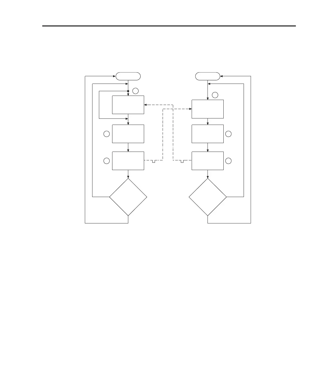
Operation model for triggering example
Details of this testing process are explained in the following paragraphs and are referenced
to the operation model shown in Figure 7-9.
A. Operation of the Model 6487 starts at point A in the flowchart where it waits for
an external trigger.
B. Pressing STEP takes Model 7001/7002 out of idle and places operation at point
B in the flowchart.
C. For the first pass through Model 7001/7002, the scanner does not wait at point
B. Instead, it closes the first channel (point C).
D. After the relay settles, Model 7001/7002 outputs a trigger pulse. Since the
instrument is programmed to scan 10 channels, operation loops back to point B
where it waits for an input trigger.
E. and F. With the Model 6487 at point A, the output trigger pulse from Model 7001/7002
triggers a measurement of DUT #1 (point E). After the measurement is com-
plete, the Model 6487 outputs a trigger pulse and then loops back to point A
where it waits for another input trigger.
Idle
Bypass
B
Wait for
Trigger Link
Trigger
Scan
Channel
C
Output
Trigger
Trigger
D
No
Scanned
10
Channels
?
Yes
7001or 7002
Make
Measurement
Made
10
Measurements
?
6487
Press STEP to start scan
A
Wait for
Trigger Link
Trigger
E
Output
Trigger
Trigger
F
No
Yes
Idle

 Loading...


