G-8 Applications Guide Model 6487 Reference Manual
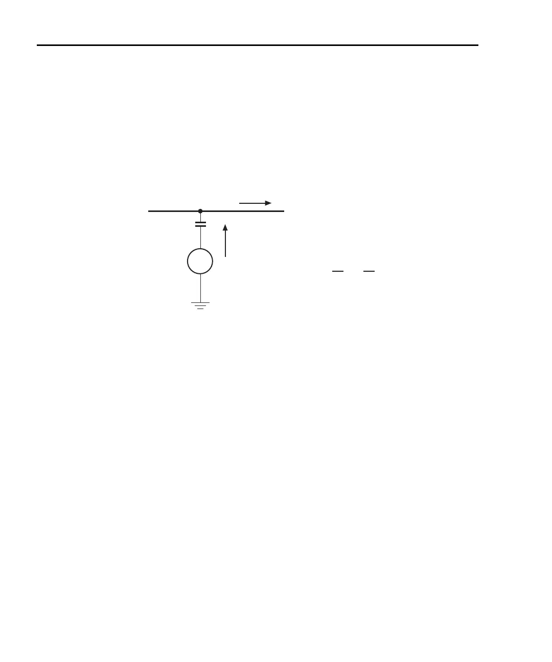
Figure G-4 shows an example of AC electrostatic coupling. An electrostatic voltage
source in the vicinity of a conductor, such as a cable or trace on a PC board, generates a
current proportional to the rate of change of the voltage and of the coupling capacitance.
This current can be calculated with the following equation:
Figure G-4
Electrostatic coupling
For example, two conductors, each with lcm
2
area and spaced lcm apart by air, will have
almost 0.1pF of capacitance. With a voltage difference of 100V and a vibration causing a
change of capacitance of 0.01pF/second (a 10% fluctuation), a current of 1pA will be
generated.
To reduce the effects of the fields, a shield can be built to enclose the circuit being mea-
sured. The easiest type of shield to make is a simple metal box or meshed screen that
encloses the test circuit. Shielded boxes are also available commercially.
Figure G-5 illustrates an example of shielding. Made from a conductive material, the
shield is always connected to the low impedance input of the electrometer or picoammeter.
If circuit low is floating above ground, observe special safety precautions to prevent any-
one from touching the shield, such as triaxial cable with the outer shield at earth potential.
iC
dV
d
-------
V
dC
dt
-------
+=
V
Coupling
capacitance
Electrostatic
voltage source
Ground-referenced
signal conductor
C
i
i = C + V
dV
dt
dC
dt
 Loading...


