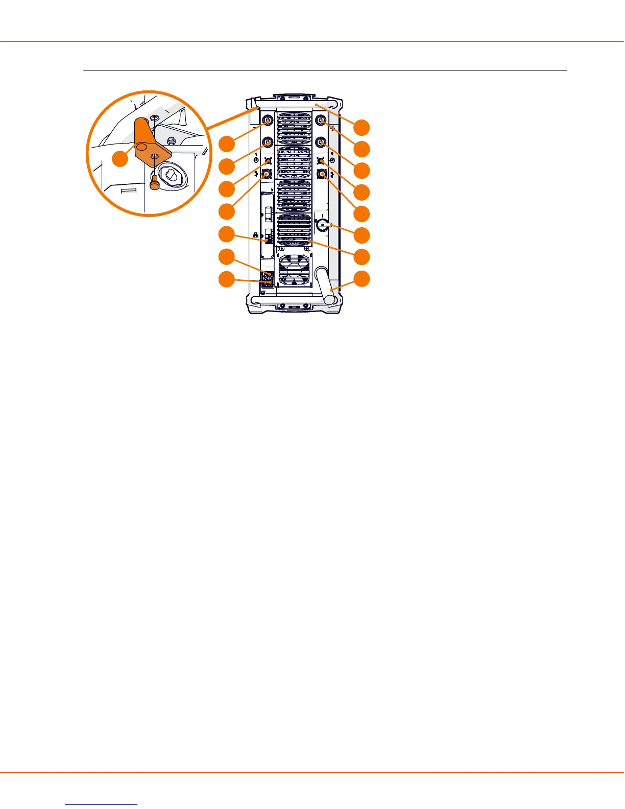
X8 MIG WELDER 2.3 System structure
Rear
6
2
3
3
2
4
4
8
5
5
9
7
10
1
11
12
1. Transportation handle
2. Welding current cable connectors (positive pole)
3. Earth return cable connectors (negative pole)
4. Measurement cable connectors
Connectors for wire feeder 1 on the left, wire feeder 2 on the right side of the power source.
5. Control cable connectors
Connectors for wire feeder 1 on the left, wire feeder 2 on the right side of the power source.
6. Ethernet connector
7. Power switch
8. Coolant outlet hose connector
9. Coolant inlet hose connector
10. Rear panel
11. Mains cable
12. Strain relief holder
OPERATING MANUAL | EN 13
©
KEMPPI 2017 | 1817

 Loading...