Keyscan Inc. – Technical Guide (PC109x - 04.15)
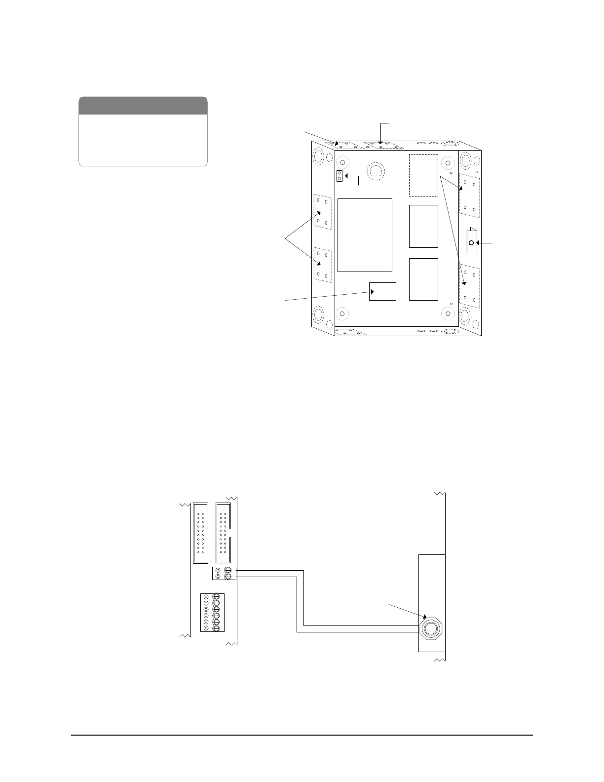
Figure 11 – EC2500 with Board Mounting Positions
Connect Enclosure Tamper Switch to TB3
Connect the yellow wires from the tamper switch to the control board’s TB3 terminal block as illustrated in the
diagram below. Please remember that this is a requirement for compliance with the following standards: UL
STD 294, CSA STD C22.2, CE, or FCC 15 Subpart B.
Figure 12 – Enclosure Tamper Switch Connected to TB3 Terminal
Front View
Cover not shown
Tamper
Switch
1 x EC2500B control board
2 x OCB-8
1 x DPS-15 power supply
1 x metal enclosure
EC2500B
Control
Board
OCB-8
Optional
OCB-8
Locations
Ground Lug
OCB-8
NETCOM
PC109x
Parts
DPS-15
power supply
KI-00115E-09-12
Optional
NETCOM*
Locations
* NETCOM - use terminal block
connections only, not 9-pin male
connector. (NETCOM refers to
NETCOM2 & NETCOM6)
CIM
or
NETCOM
CONTROL 1
CTS
DTR
DCD
RD
TD
GND
RS-232 (COM4)
TAMPER TB3
SWITCH
+
-
Connect the yellow wires on the tamper
switch to TB3 terminal on the control board.
Protective
Cover
Metal
Enclosure
Tamper Switch
PC109x
Control Board
Cut View
KI-00116E-04-13
CONTROL 4