Keyscan Inc. – Technical Guide (PC109x - 04.15)
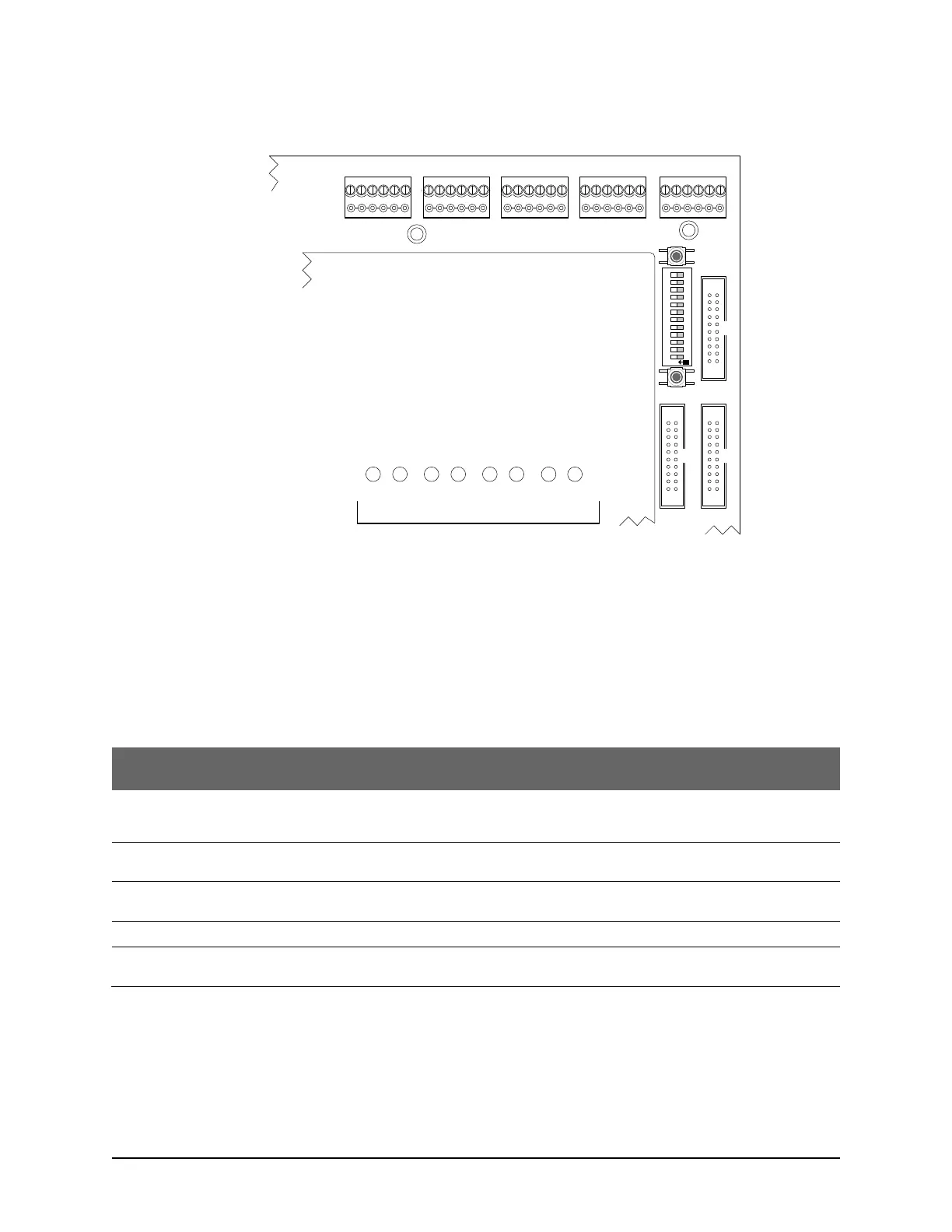
Figure 57 - Communication LEDs - CA & EC Control Boards
System Status LED
The system status LED is multi-color – red, amber and green – indicating the current system status as
outlined. The control board also has a piezo that beeps under certain LED states.
Table 19 - System Status LED
The main processor is held in reset and not operating. This can be caused when S1 is depressed or the
main processor supervisory circuit’s critical PCB voltages are not within normal operating parameters. The
on-board piezo emits a steady tone while in this mode.
The CA or EC control board is in clear memory mode. The on-board piezo emits a cycle of 2 short beeps
and then a pause while the control board is in this mode.
The CA or EC control board has not communicated to the Client software since its last system reset or
clear memory.
The CA or EC control board’s last communication with the Client software was 3 minutes or greater.
The CA or EC control board has communicated to the Client software since its last system reset or clear
memory.
COMMUNICATION STATUS
TD1 RD1 TD2 RD2 TD3 RD3 TD4 RD4
READER 1READER 2READER 3READER 4READER 5
CONTROL 2
CONTROL 5
CONTROL 3
ACU Protective
Cover
Cut View of
CA8500B
COM LEDs are in the same
location on all CA & EC
control boards.
Location of COM LEDs
KI-00188E-04-13
S1
S2
S3
O
N
1 2 3 4 5 6 7 8 9 10 11 12