Keyscan Inc. – Technical Guide (PC109x - 04.15)
Serial Communication
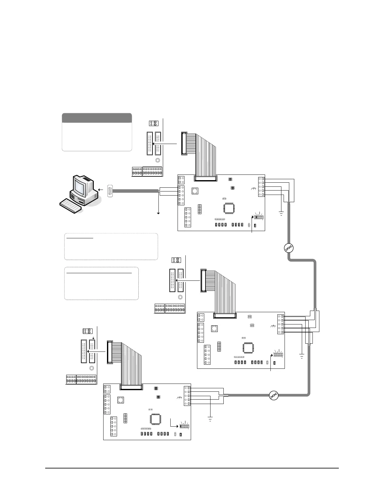
Serial communication is a direct serial connection from the PC to the CIM unit using a 9-pin RS-232 data cable
with five (5) conductors - Keyscan part # 40-2322. A Communication Manager must be installed on the PC
that has the direct serial connection to CIM 0.
Figure 50 – PC Serial Connection with multiple CIMs/ACUs
CIM 0
Jumper ON J4
COMMON AUX INPUTS - E
17 18 19 20 21 22 23 24
IOCB (COM1)
RX
TX
CPB/CB COMMS
(COM4)
H2
COMMON AUX INPUTS - E
17 18 19 20 21 22 23 24
IOCB (COM1)
RX
TX
CPB/CB COMMS
(COM4)
TD1
RD1
TD2
RD2
GND
RTS
CTS
GND
RTS
CTS
B3 B2 B1B0
Diag
J2
RESET
-
CAN2
+
EGND
-
CAN1
+
GND
V +
(+12V)
SCKT1
PC106x
J1
J7
J8
J6
J5
CAN2
CAN1
1 2 1 2 1 2 1 2
Rx-COM
COM
CAN CAN-Tx
J3
J4
J9
J12
Power
Good
Fault
HDR1
J10
J11
TD1
RD1
TD2
RD2
GND
RTS
CTS
GND
RTS
CTS
B3 B2 B1B0
Diag
J2
RESET
-
CAN2
+
EGND
-
CAN1
+
GND
V +
(+12V)
SCKT1
PC106x
J1
J7
J8
J6
J5
CAN2
CAN1
1 2 1 2 1 2 1 2
Rx-COM
COM
CAN CAN-Tx
J3
J4
J9
J12
Power
Good
Fault
HDR1
J10
J11
Black
Green
Red
to COM port
CIM 0
CIM 1
CIM n
White Orange
Orange
Blue
White Blue
White Orange
Orange
Blue
White Blue
Ground
White Orange
Orange
Blue
White Blue
Ground
Match baud rate on control board J16 to baud
rate on CIM J9 – J12
Slave
Global
Master
Ground
Termination Jumpers ON
J5 & J6 / J7 & J8
first & last CIM
Connect EGND terminal on all CIMs to
ground lugs in ACU metal enclosures.
Global Master
Jumper ON - J3
CAT 5
CAN Bus
Slave - Jumper OFF - J3
Bit Rate / Distance
Bit CAN Bus RS-232
9600 3280' (999.7 m) 49.2' (14.9 m)
19200 3280' (999.7 m) 49.2' (14.9 m)
57600 984' (299.9 m) 26.2' (7.9 m)
115200 262' (80 m) 9.84' (3 m)
Bit Rate / Jumper Settings (0 = OFF / 1 = ON)
Bit CIM Control Board
J9 J10 J11 J16 – 1 2 6
9600 0 0 1 0 0 0
19200 0 1 0 0 1 0
57600 1 0 0 0 0 1
115200 1 0 1 0 1 1
H2
H2
KI-00269E-07-12
Shield*
to ACU
ground
lug
*Insulate shield with PVC tubing such as
Alpha (p/n PVC10516 16AWG) or
comparable insulator.
RS-232 - 5 conductor
shielded 22 AWG cable
CAT 5
CAN Bus
Termination Jumpers ON
J5 & J6 / J7 & J8
first & last CIM
Slave
H1
Slave - Jumper OFF - J3
H1
H1
- RS-232 Data Cable
- Control Board
- PC
- CIM
- CAT 5 Cable – 2 twisted pairs
Parts List
PC with
Communication
Manager