Keyscan Inc. – Technical Guide (PC109x - 07.15)
CIM Jumper Settings
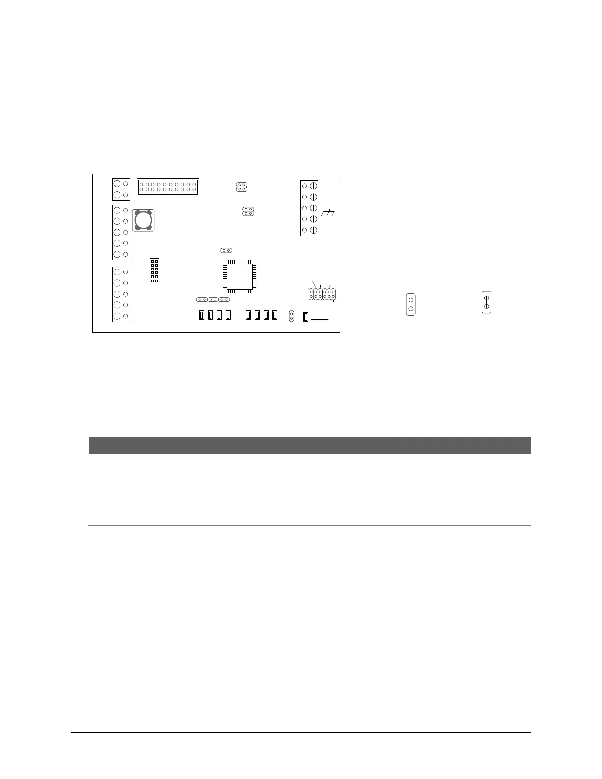
The CIM has jumpers that determine the board's attributes. Ensure the necessary jumpers are set depending
on the position and function the board is serving. Jumper settings are reviewed in the following tables. Please
note the jumper locations in the diagram below.
Figure 78 – CIM Jumper Locations
CIM Global Master Jumper – J3 (Master/Slave ACUs)
Jumper J3 sets the CIM as global master. Designate only one (1) CIM as a global master. Designate all other
CIMs as slaves.
Table 17 – CIM Global Master Jumper J3
Set global master CIM at least busiest ACU. Set global
master CIM connected to door control unit only when using
ACU to ACU communication on CAN Bus 2.
Do not set a CIM as global master that is connected to an
elevator control unit. See note below.
Note
On a communication bus with elevator control units only, a global master CIM is not applicable. Do not
place a jumper on J3.
Jumper Off
Off = 0
Jumper On
On = 1
Jumper Legend
J1 – Reset
J2 – Diagnostic mode selection
J3 – Global master/slave selection
J4 – CIM 0 selection (module with network
or serial connection)
J5 & J6 – CAN Bus 1 termination selection
J7 & J8 – CAN Bus 2 termination selection
J9 – J11 – Serial bit rate selection
J12 – Program mode with mounted
NETCOMP
CIM Jumper Locations
KI-00262E-07-13
TD1
RD1
TD2
RD2
GND
RTS
CTS
GND
RTS
CTS
B3 B2 B1 B0
Diag
J2
RESET
-
CAN2
+
EGND
-
CAN1
+
GND
V +
(+12V)
SCKT1
PC106x
J1
J7
J8
J6
J5
CAN2
CAN1
1 2 1 2 1 2 1 2
Rx - COM COM
CAN
CAN - Tx
J3
J4
J9
J12
Power
Good
COM1
COM2
HDR1
J10
J11
Fault
(Flashing)