Keyscan Inc. – Technical Guide (PC109x - 07.15)
Connect Enclosure Tamper Switch to TB3
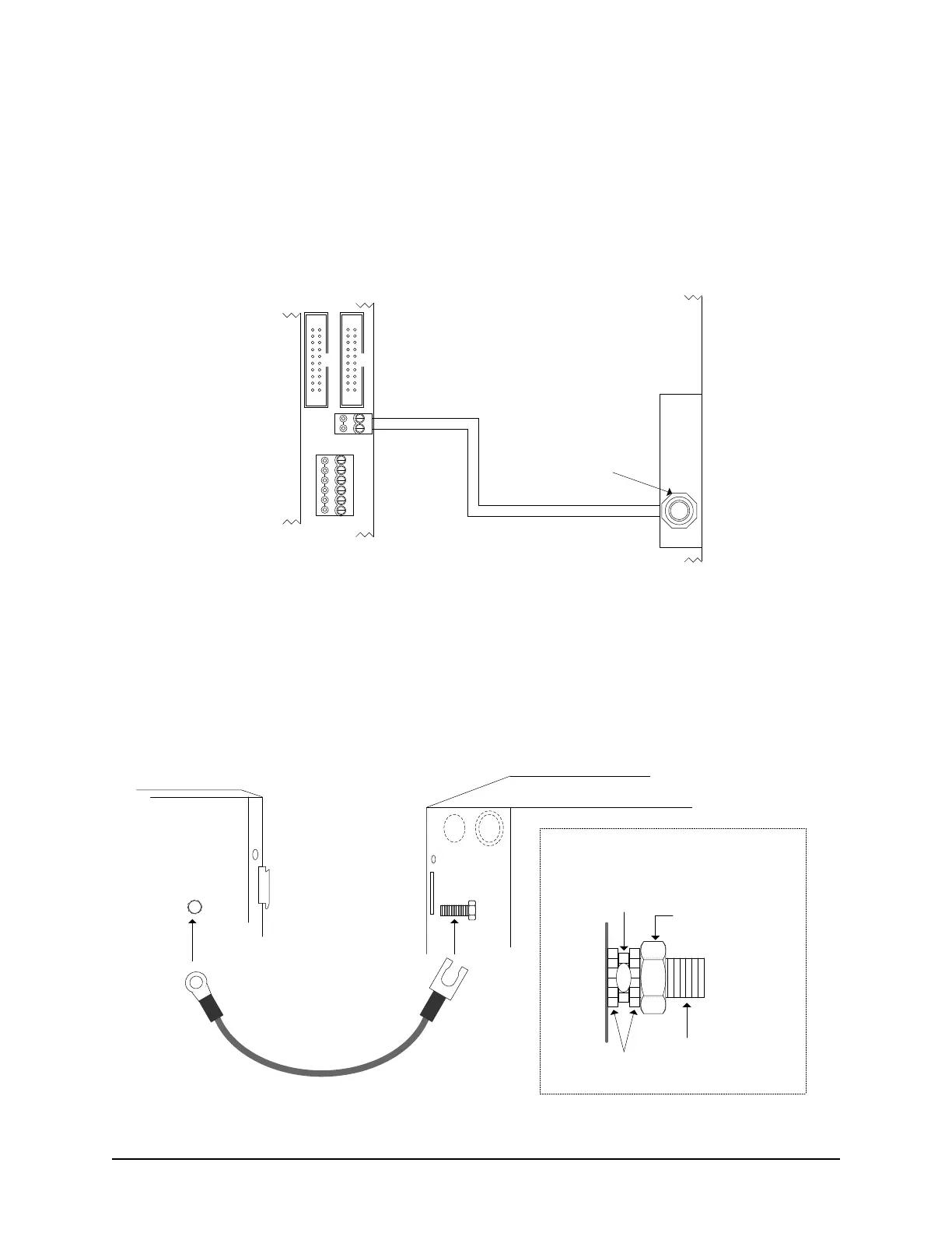
Connect the yellow wires from the tamper switch to the control board’s TB3 terminal block as illustrated in the
diagram below. Please remember that connecting the tamper switch, the ground strap and securing the
enclosure cover are all requirements for compliance with the following standards: UL STD 294, CSA STD
C22.2, CE, or FCC 15 Subpart B.
Figure 12 – Enclosure Tamper Switch Connected to TB3 Terminal
Connect Enclosure Ground Strap
Connect the enclosure ground strap to the designated studs on both the metal enclosure and the enclosure
cover. Position the cable lug between two star washers and securely tighten with a nut as illustrated in the
diagram below.
Figure 13 – Enclosure Ground Strap Connection
CONTROL 1
CTS
DTR
DCD
RD
TD
GND
RS-232 (COM4)
TAMPER TB3
SWITCH
+
-
Connect the yellow wires on the tamper
switch to TB3 terminal on the control board.
Protective
Cover
Metal
Enclosure
Tamper Switch
PC109x
Control Board
Cut View
KI-00116E-04-13
CONTROL 4
Enclosure Ground Strap
Enclosure Cover
Metal Enclosure
Use the enclosed star
washers and nuts to
secure both ends of the
cable to the studs as
shown on the right.
Stud
Stud
Star
Washers
Nut
Cable
Lug
Stud
Side View of Stud with Cable Lug Connection
KI-00117E-07-11