Keyscan Inc. – Technical Guide (PC109x - 07.15)
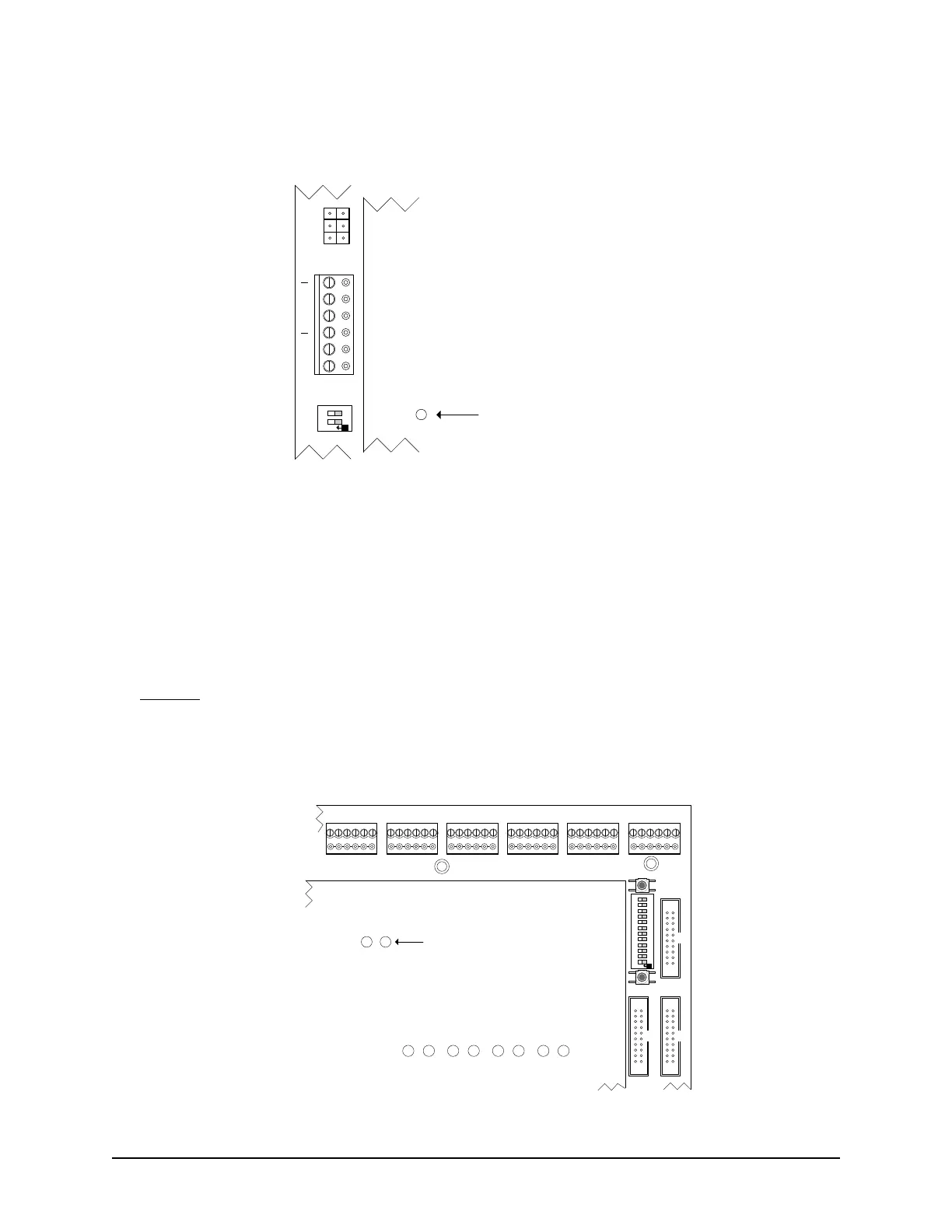
Figure 89 - Location of System Status LED
Card Diagnostics - LED Wiegand Bit Counters
CA and EC control boards have LED Wiegand bit counters – 10s and 1s – to determine card binary bits. You
must be able to observe the control board to do this procedure. To verify the binary bits, present the card or
tag at the reader and count the number of times each LED blinks.
10s count the 1
st
binary digit
1s count the 2
nd
binary digit
Example
If the 10s LED blinks 3 times and the 1s LED blinks 6 times, the card has 36 binary bits (36-bit Wiegand
card).
Figure 90 – Location of Wiegand Bit Counter LEDs
PSC1
READER PWR
SYSTEM STATUS
ACU Protective Cover
System Status LED
KI-00191E-04-13
ACU PWR
+
FAIL
+
FAIL
Cut View
PC109x Control Board
S4
1 2
O
N
COMMUNICATION STATUS
TD1 RD1 TD2 RD2 TD3 RD3 TD4 RD4
READER 1READER 2READER 3READER 4READER 5
CONTROL 2
CONTROL 5
CONTROL 3
Protective ACU Cover
Cut View of
CA8500B
KI-00147E-04-13
READER 6
CARD
BITS
10s 1s
Wiegand
Bit Counter
LEDs
S1
S2
S3
O
N
1 2 3 4 5 6 7 8 9 10 11 12