Keyscan Inc. – Technical Guide (PC109x - 07.15)
Control Board – Mounting Locations
The following diagrams illustrate the mounting positions for control board series CA250, CA4500, CA8500,
EC1500 and EC2500 units. Illustrations also show mounting positions for communication boards and output
control boards (OCB-8). Different door control board series – CA250, CA4500, and CA8500 – can be used
within the same communication loop.
CA & EC Control Board Dimensions
Width 20.35 cm (8.01 inches)
Height 28.9 cm (11.38 inches)
Operating Environment – ACUs & ECUs
Temperatures: 41°F to 120°F (5°C to 49°C)
Humidity: 0% to 90% R.H., non-condensing
Important
Do not mount close to high voltage equipment.
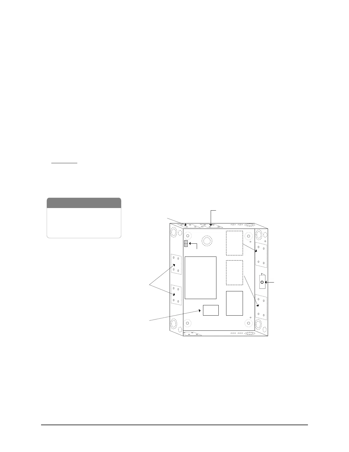
Figure 7 – CA250 with Board Mounting Positions
Front View
Cover not shown
Tamper
Switch
CIM
or
NETCOM
1 x CA250B control board
1 x OCB-8
1 x DPS-15 power supply
1 x metal enclosure
CA250B
Control
Board
OCB-8
Optional
OCB-8
Locations
Optional
OCB-8
Locations
Ground Lug
NETCOM
* NETCOM - use terminal block
connections only, not 9-pin male
connector. (NETCOM refers to
NETCOM2 & NETCOM6)
PC109x
Parts
DPS-15
power supply
KI-00111E-09-12
Optional
NETCOM*
Locations