Keyscan Inc. – Technical Guide (PC109x - 07.15)
colour assignments on the following diagram. When possible, use a Keyscan 9-pin RS-232 data cable (Keyscan
part # 40-2322) manufactured specifically for Keyscan serial data connectivity.
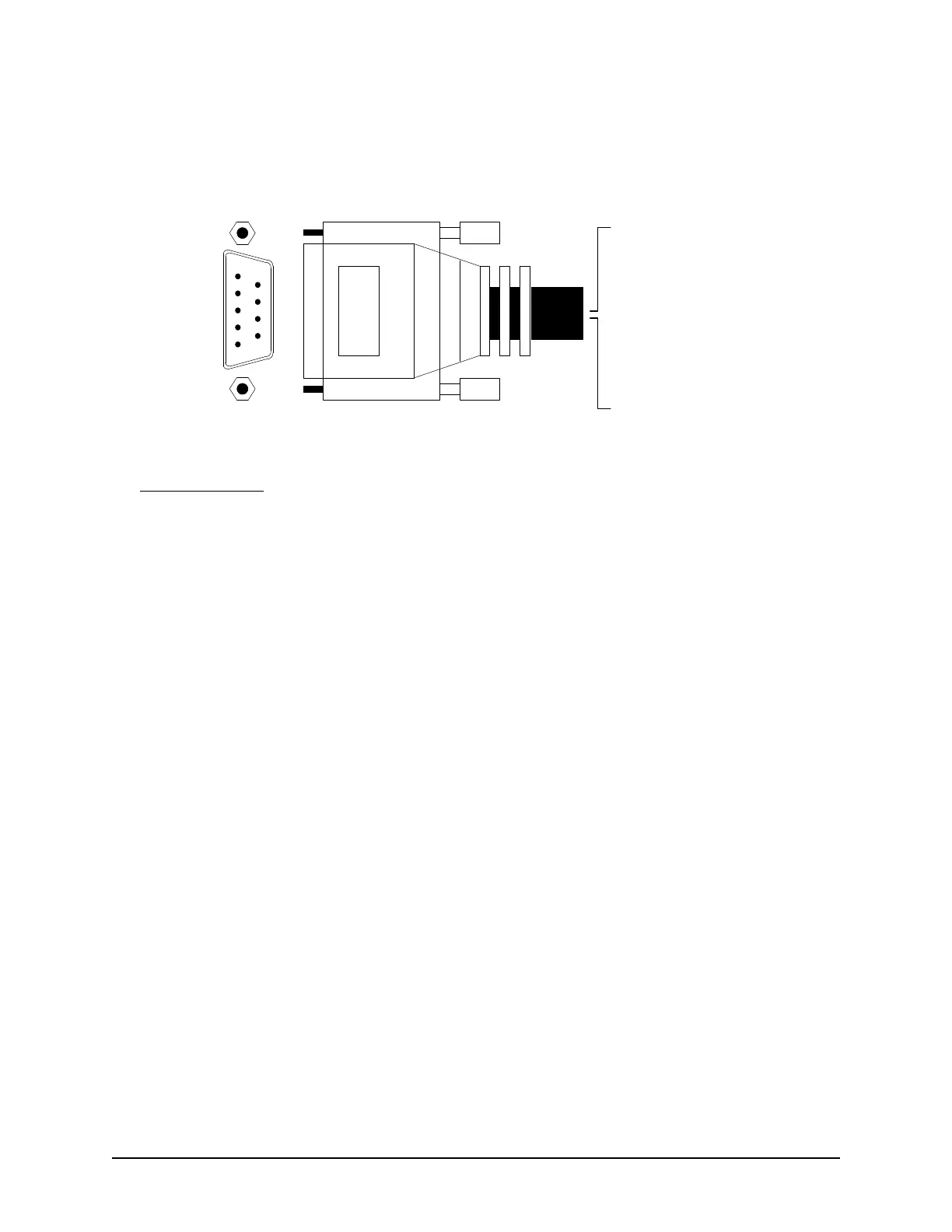
Figure 72 – RS-232 Data Cable Connections
Installation Notes
Typically, the black wire of the RS-232 cable from the PC, which is the receive data input of the PC, is
connected to the serial port TD pin of most Keyscan products.
Typically, the red wire of the RS-232 cable, which is the transmit data output of the PC, is connected to
the RD pin of most Keyscan products.
- Shield
1 - White
2 - Black
3 - Red
4 - Brown
5 - Green
6 - shorted to pin 7
7 - shorted to pin 6
8 - not connected
9 - not connected
DB9 Connector
(Front View)
1
2
3
4
5
6
7
8
9
KI-00152E-07-11