Keyscan Inc. – Technical Guide (PC109x - 07.15)
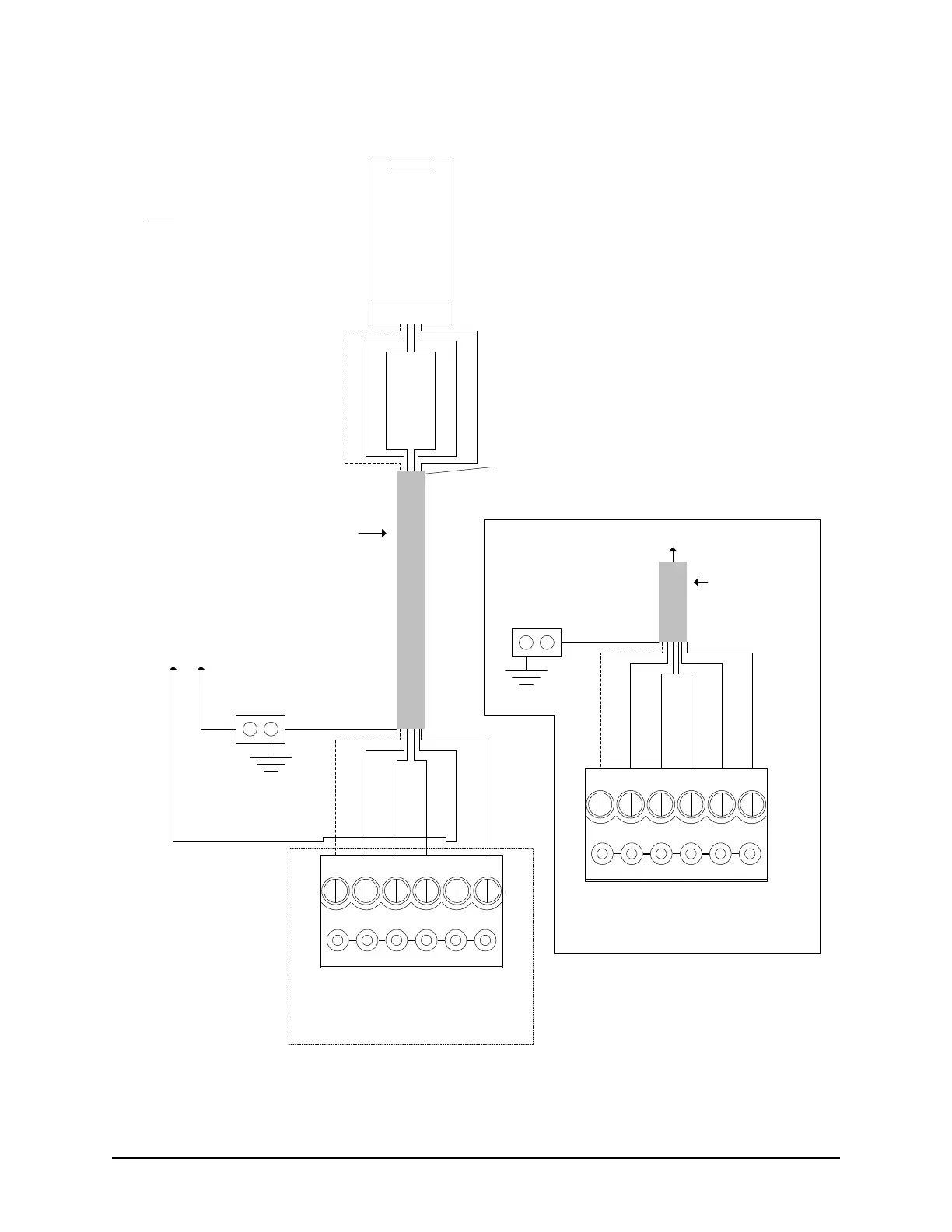
Shield not connected.
Isolate with electrical tape.
6 conductors
shielded 18 AWG
Maximum - 500 ft
(152.4 m)
Shield
ACU Ground
Lug
D1 (White)
D0 (Green)
Red
GND (Black)
LED (Orange)
Black
VDC + -
to separate
DC power
supply
PWR (Red)
Diagram illustrates connections
and cables for Rev A.
Note
Rev B & Rev C do not require
separate power supply. Connect
Red wire to PWR RED terminal
on ACU reader terminal.
Connect shield to ACU ground
lug. 18 or 22 AWG shielded
cable acceptable.
Reader terminal on control board
LED D1
WHT
D0
GRN
PWR
RED
GND
BLK
C1
(BEEP)
LED (Orange)
D1 (White)
D0 (Green)
PWR (Red)
GND (Black)
Pre-alert (Yellow)
Pre-alert
(Yellow)
Yellow (Beeper) used for pre-
alert otherwise isolate and
tape back.
If connecting external sound
device, see Pre-Alert Relay
Option or refer to ACU cut
sheet enclosed with panel for
ACU/OCB8 relay
assignments.
Note - If Pre-alert is
connected, the reader
cannot read any HID 125
kHz-compatible card during
the pre-alert beep.
KI-00206E-03-13
Shield
D1 (White)
D0 (Green)
GND (Black)
LED (Orange)
PWR (Red)
Reader terminal on control board
LED D1
WHT
D0
GRN
PWR
RED
GND
BLK
C1
(BEEP)
Pre-alert
(Yellow)
ACU Ground
Lug
6 conductors
shielded 22 AWG
Maximum - 500 ft
(152.4 m)
Rev. B & C
Connections
Rev. A Connections
to reader
Rev. A – 225 mA
Rev. B – 75 mA
Rev. C – 116 mA