Keyscan Inc. – Technical Guide (PC109x - 07.15)
Door Contacts, Exit Buttons, Auxiliary Inputs
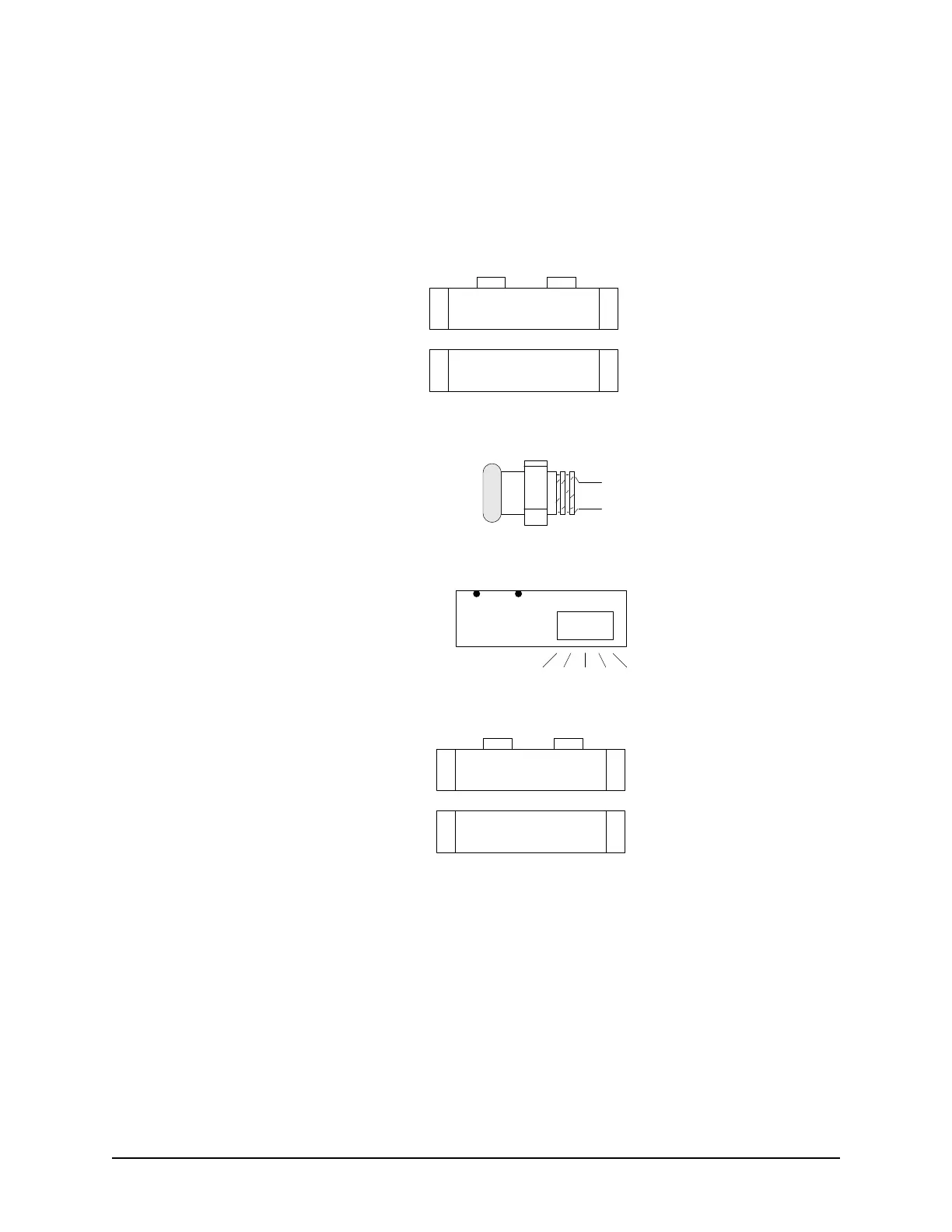
The following diagram illustrates the door contacts, exit buttons, PIRs, and auxiliary inputs. See the
manufacturer's documentation for mounting instructions. Avoid running cables parallel with AC wiring or across
fluorescent light fixtures; this causes AC induction and transmission interference.
Figure 18 – Door Contacts, Exit Buttons, PIRs, & Auxiliary Inputs
Exit Push Button
1
1
Door Contact
NC COM
Door Sensor
Door
Sensor
Auxiliary
Input
Lens
NO COM
COM
NO
PIR
RTE – ½ second pulse
Determines the amount of
time the output relays will
energize when motion is
detected.
(RTE - Request To Exit)
1
1
Aux Input
COMNC
NO = Normally Open
NC = Normally Closed
KI-00122E-07-11