Keyscan Inc. – Technical Guide (PC109x - 07.15)
Readers
Never mount readers close to high-voltage equipment. For convenient entry, mount readers on the latch side
of doors. When mounting proximity readers for monitoring in and out activity at the same door, space the
readers at a distance greater than the combined radio signal read ranges.
As an example, if the read range is 4 inches, mount the two readers at a distance greater than 8 inches from
each other. For mounting readers to a metal surface, consult with the manufacturer's documentation.
If a door/reader is located beyond the maximum cable length to the ACU, use a Keyscan WIEEX2 extender kit
to a maximum distance of 4000 feet (1219.2 m).
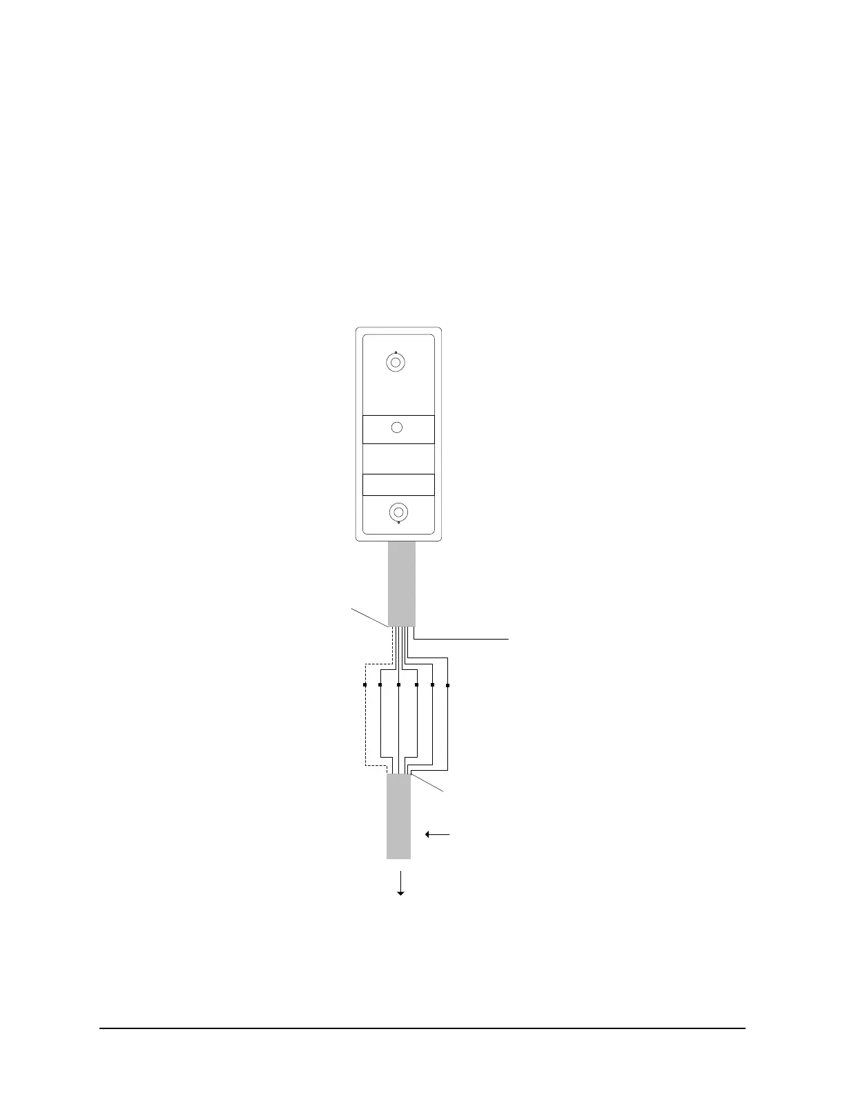
Figure 19 – Typical Door Reader Connection
Proximity Reader
(Refer to specific
Keyscan, HID & Indala
readers for wiring
connections.)
To reader terminal on
ACU
LED (Brown)
D1 (White)
D0 (Green)
PWR (Red)
GND (Black)
Shield not connected.
Isolate with electrical tape.
6 conductors shielded 18 or 22 AWG
Maximum 500 ft (152.4 m)
Blue used for pre-
alert otherwise
isolate and tape
back.
Orange not
used. Isolate
and tape back.
KEYSCAN
Pre-alert (Blue)
Shield not connected.
Isolate with electrical tape.
KI-00123E-07-11