System Interconnects 4
TS-5020 Automotive Electronics Functional Test System Wiring Guide and Hardware Reference 4-19
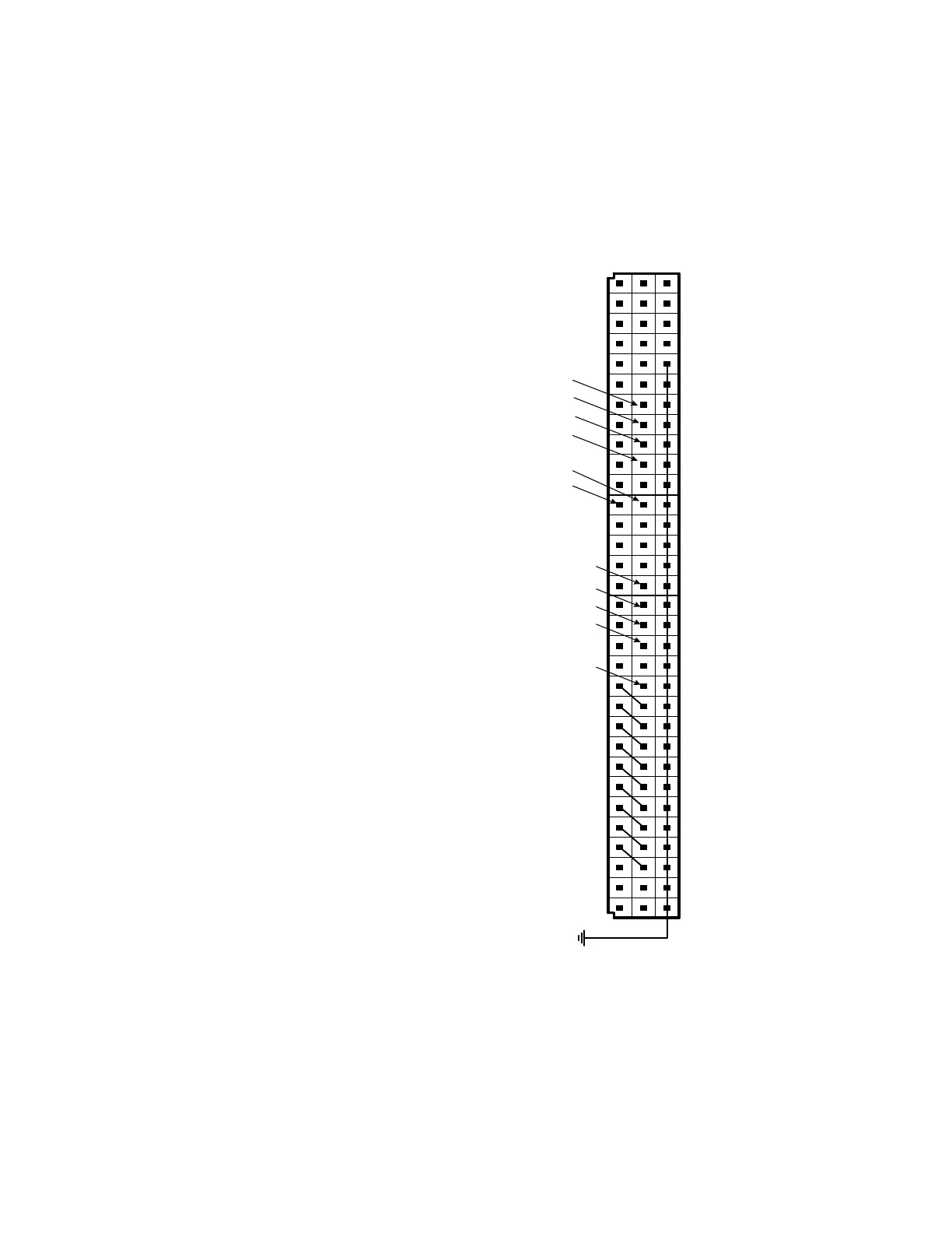
Figure 4-17 TS-5020 System Connector (J6 or J60) TC
n
Assignments
Notes:
[1] Available for user’s configuration. Refer to Figure 4-11 for
TC pins mapping.
[2] Refer to Figure 4-12 for TC pins mapping.
19 20191817161514131211108765432 2928272625242322 3221 3130
System Ground
TS-5020 System
Connector (Syscon)
Spare Inst. #1
Spare Inst. #7
Spare Inst. #6
Spare Inst. #5
Spare Inst. #4
Spare Inst. #3
Spare Inst. #2
DAC Common or Spare Inst. #10
DAC Channel 1 or Spare Inst.
#9
DAC Channel 1 or Spare Inst. #8
Top View
Not Used (Trigger #1)
[1]
Not Used (Trigger #2)
[1]
Not Used (Trigger #3)
[1]
Not Used (Trigger #4)
[1]
Not Used
Not Used
Not Used
Not Used
Not Used (ARB Low)
[1]
Not Used (ARB High)
[1]
Not Used (Aux #4)
[2]
Not Used (Aux #3)
[2]
Not Used (Aux #2)
[1]
Not Used (Aux #1)
[1]