119
Measuring Digital Communications Signals
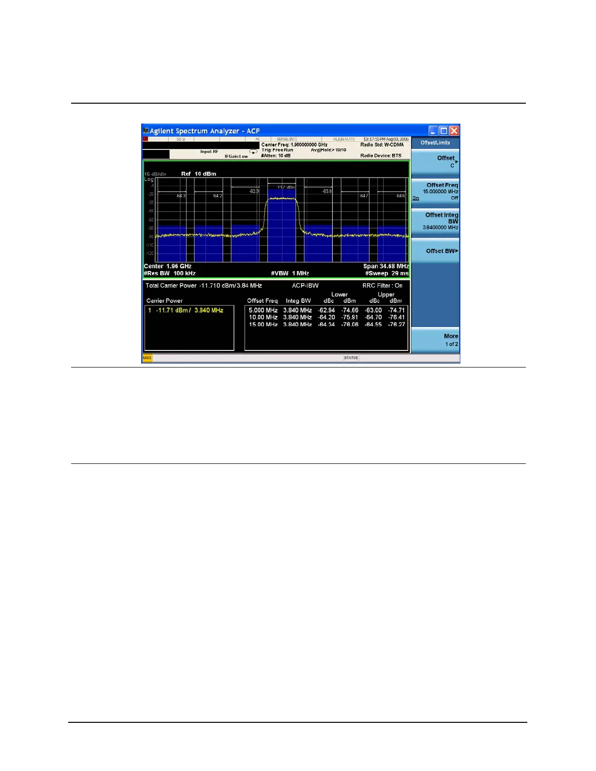
Making Adjacent Channel Power (ACP) Measurements
Figure 9-4 Measuring a Third Adjacent Channel
12Set pass/fail limits for
each offset.
• Press Meas Setup,
Offset/Limits, Offset, A,
More, Rel Limit (Car),
−55, dB, Offset, B, Rel
Limit (Car), −75, dB,
Offset, C, Rel Limit (Car),
−60, dB.
13Turn the limit test on. • Press Meas Setup, More,
Limit Test (On).
In Figure 9-5 notice that offsets A and
C have passed, however offset B has
failed. Power levels that fall above our
specified –75 dB for offset B, fail. The
offset bar graph and the associated
power level value are shaded red to
identify a failure. The offset limits are
shown as dashed lines.
Step Action Notes

 Loading...


