118
Measuring Digital Communications Signals
Making Adjacent Channel Power (ACP) Measurements
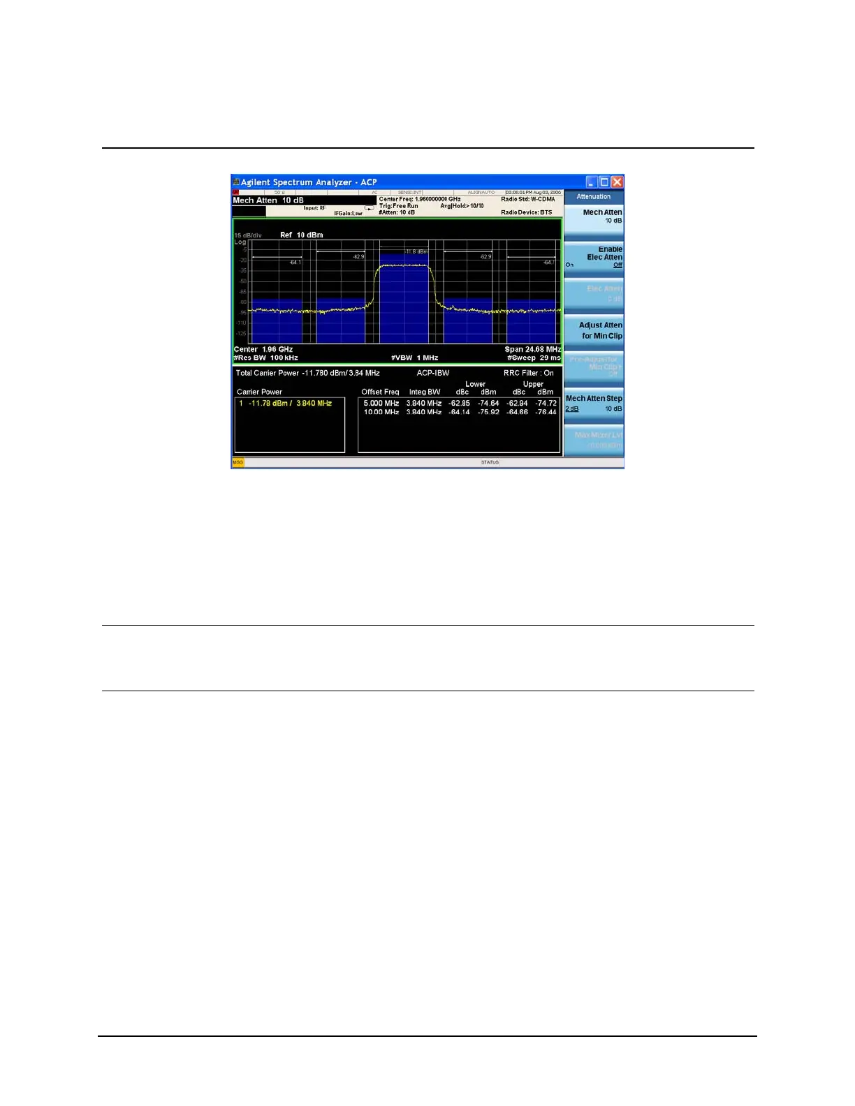
Figure 9-3 ACP Measurement on a Base Station W-CDMA Signal
Two vertical white lines, in the center of the screen, indicate the bandwidth limits of the central channel being
measured.
The frequency offsets, channel integration bandwidths, and span settings can all be modified from the default
settings.
Offsets A and B are designated by the adjacent pairs of white lines, in this case: 5 MHz and 10 MHz from the
center frequency respectively.
10View the results using the
full screen.
• Press Full Screen. Press the Full Screen key again to
exit the full screen display without
changing any parameter values.
11 Define a new third pair of
offset frequencies.
• Press Meas Setup,
Offset/Limits, Offset, C,
Offset Freq (On), 15, MHz.
This third pair of offset frequencies is
offset by 15.0 MHz from the center
frequency (the outside offset pair) as
shown in Figure 9-4 Three further
pairs of offset frequencies (D, E and F)
are also available.
Step Action Notes

 Loading...


