202
Concepts
Time Gating Concepts
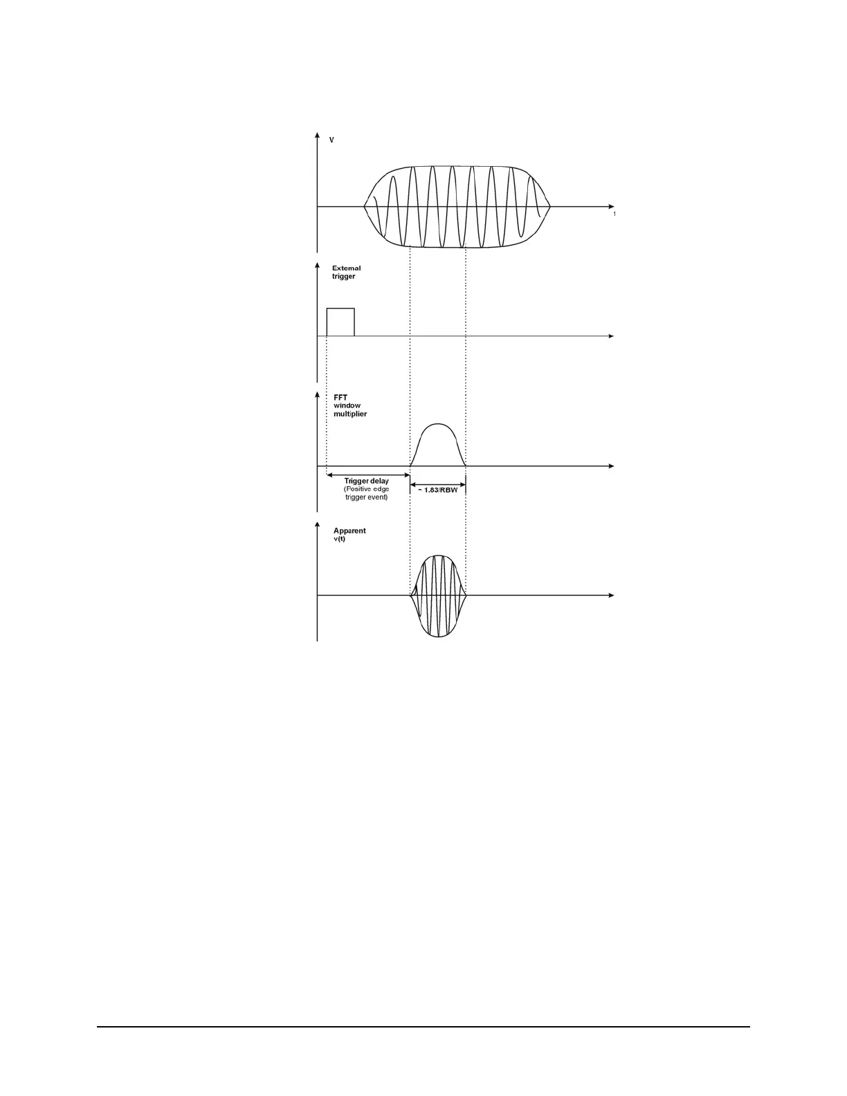
Figure 15-10 Gated FFT Timing Diagram
Time gating basics (Gated LO and Gated Video)
The gate passes or blocks a signal with the following conditions:
• Trigger condition - Usually an external transistor-transistor logic (TTL) periodic
signal for edge triggering and a high/low TTL signal for level triggering.
• Gate delay - The time after the trigger condition is met when the gate begins to
pass a signal.
• Gate length - The gate length setting determines the length of time a gate begins
to pass a signal.
To understand time gating better, consider a spectrum measurement performed on
two pulsed-RF signals sharing the same frequency spectrum. You will need to
consider the timing interaction of three signals with this example:
• The composite of the two pulsed-RF signals.
• The gate trigger signal (a periodic TTL level signal).

 Loading...


