203
Concepts
Time Gating Concepts
• The gate signal. This TTL signal is low when the gate is “off” (blocking) and
high when the gate is “on” (passing).
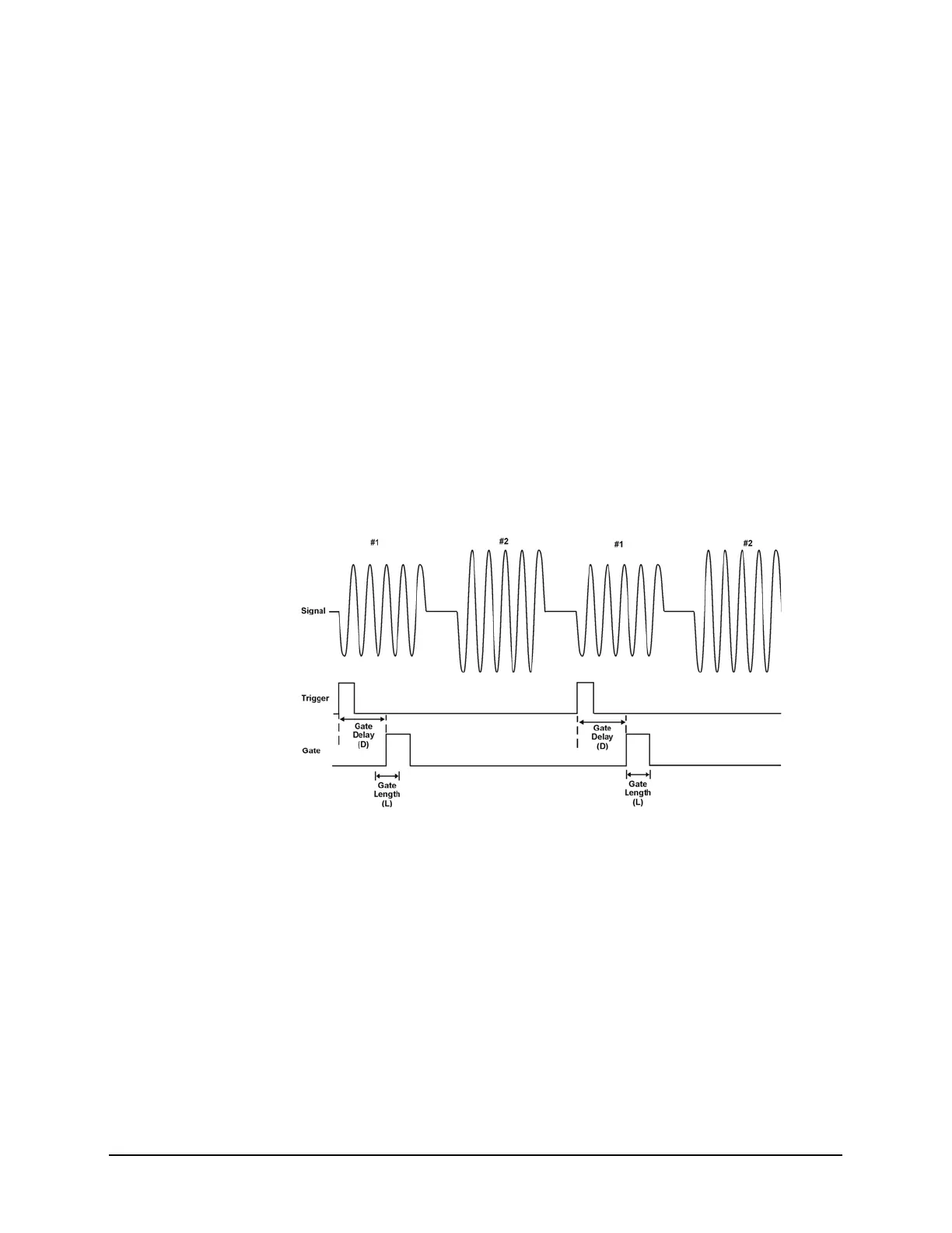
The timing interactions between the three signals are best understood if you observe
them in the time domain (see Figure 15-11).
The main goal is to measure the spectrum of signal 1 and determine if it has any
low-level modulation or spurious signals.
Because the pulse trains of signal 1 and signal 2 have almost the same carrier
frequency, their spectra overlap. Signal 2 will dominate in the frequency domain due
to its greater amplitude. Without gating, you won't see the spectrum of signal 1; it is
masked by signal 2.
To measure signal 1, the gate must be on only during the pulses from signal 1. The
gate will be off at all other times, thus excluding all other signals. To position the
gate, set the gate delay and gate length, as shown in Figure 15-11, so that the gate is
on only during some central part of the pulse. Carefully avoid positioning the gate
over the rising or falling pulse edges. When gating is activated, the gate output signal
will indicate actual gate position in time, as shown in the line labeled “Gate.”
Figure 15-11 Timing Relationship of Signals During Gating
Once the signal analyzer is set up to perform the gate measurement, the spectrum of
signal 1 is visible and the spectrum of signal 2 is excluded, as shown if Figure 15-13
In addition, when viewing signal 1, you also will have eliminated the pulse spectrum
generated from the pulse edges. Gating has allowed you to view spectral components
that otherwise would be hidden.

 Loading...


