ENGLISH
Chapter 2: Installaon
DVR User’s Manual
23
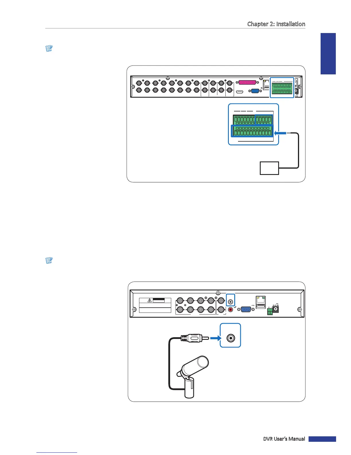
2.6 Connecng the Sensors
Note:
Available in 16-channel DVRs only.
You can connect sensors up to
16 channels. The connectors are
labelled according to channels.
VGA
AUDIO IN (CH5-CH16)
HDMI
LAN
1
2
AUDIO OUTVIDEO OUT AUDIO IN
2
4
1
3
MAIN
SPOT
CH8
CH16
CH7
CH15
CH6
CH14
CH5
CH13
CH4
CH12
CH3
CH11
CH2
CH10
CH1
CH9
G12345678910 11
+
-
NO COM G1615141312
RS-485
D+ D
-
KB OUT IN
ALARM
12V
G 12345678910 11
+
-
NO COM
G1615141312
RS-485 OUT
D
+
D
-
KB IN
ALARM
Sensor device
(input)
16-Channel DVR
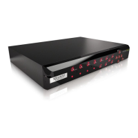
2.7 Connecng the Microphones
The DVR supports up to 16 audio input channels. Microphones can be connected directly via RCA, BNC, or through the
parallel audio input connecon.
2.7.1 RCA Connecon
Note:
Available in 8-channel and 4-channel DVRs only.
RS-485
3
4
1
2
1
2
VIDEO
OUTPUT
7
8
5
6
VIDEO INPUT AUDIO
OUTPUT
AUDIO
INPUT
VGA
12V
LAN
CAUTION
RISK OF ELECTRIC SHOCK
DO NOT OPEN
CAUTION: TO REDUCE THE RISK OF ELECTRICAL SHOCK.
DO NOT OPEN COVERS. NO USER SERVICEABLE
PARTS INSIDE. REFER SERVICING TO QUALIFIED
SERVICE PERSONNEL.
WARNING: TO PREVENT FIRE OR SHOCK HAZARD. DO NOT
EXPOSE UNITS NOT SPECIFICALLY DESIGNED FOR
OUTDOOR USE TO RAIN OR MOISTURE.
AUDIO
INPUT
Microphone
RCA audio cable
4-Channel / 8-Channel DVR
Connect the microphone(s) using
RCA cable connecon as shown.