PCR-M 31
Chapter 2 Installation and Preparation
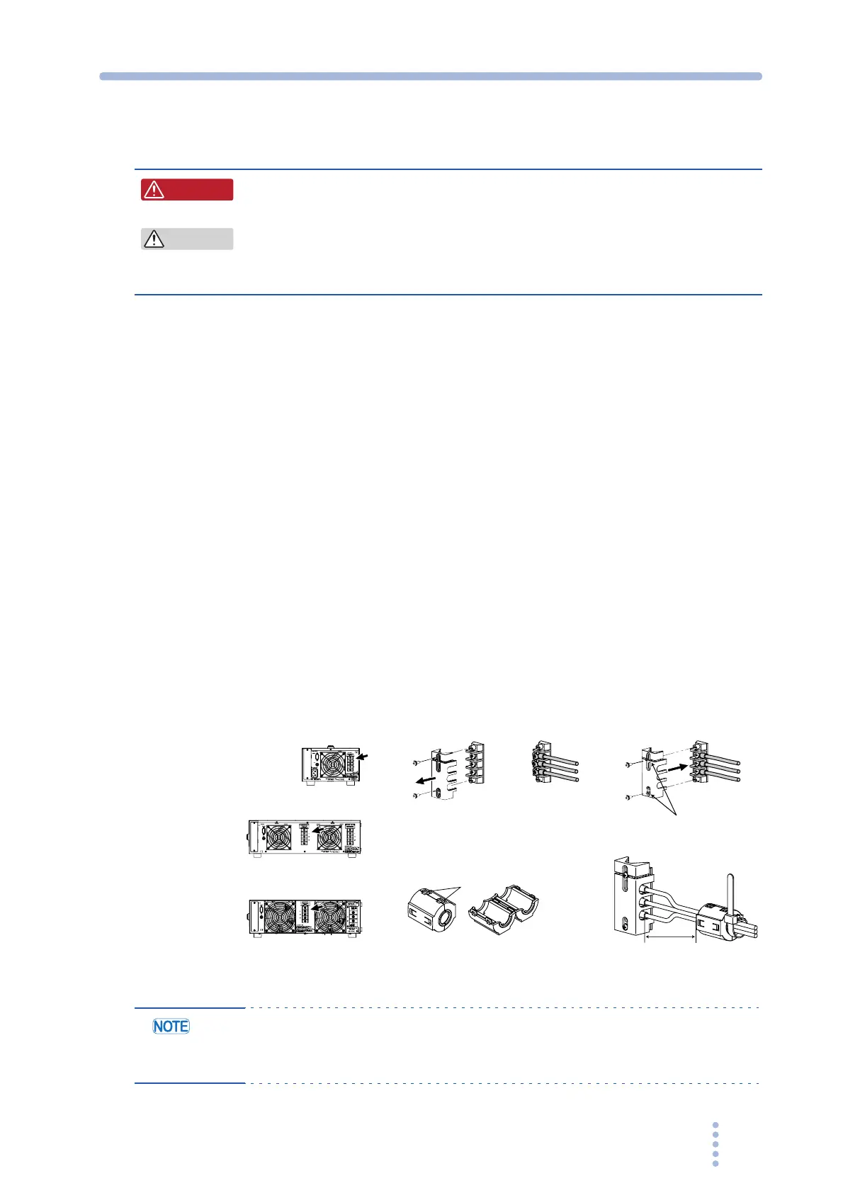
Connecting the load cables and attaching the Ferrite Core
Attachment of the ferrite core is only PCR2000M.
• There is a danger of electric shock. Do not use the terminal block
with the terminal cover removed.
• In DC mode, L is at positive potential and N is at negative potential when setting
the positive value. L is at negative potential and N is at positive potential when
setting the negative value.
1.
Check that the POWER switch is turned off.
2.
Remove the terminal cover that is attached to the OUTPUT terminal
block.
3.
Securely connect the load wires to the OUTPUT terminal block.
If the load has a ground (GND) terminal, be sure to connect it to the G terminal of the
PCR-M OUTPUT terminal block. Be sure to use a wire that is greater than or equal to
the diameter of the wires used to connect the load.
4.
Attach the terminal cover that you removed in procedure 2 using the
lower holes.
It is completed of procedure for PCR500M and PCR1000M. As for PCR2000M, it is
required to attach the ferrite core to the load wire.
5.
Unlock the ferrite core and open it.
6.
Close the ferrite core. Avoid catching the wire on the ferrite core.
Attach the ferrite core within 10 cm from the OUTPUT terminal block. Lock it
securely in place.
7.
To avoid moving the ferrite core, attach the cable tie to fix the position of
the ferrite core.
Fig.2-11 Connecting to the OUTPUT terminal block
• The L and N terminals of the OUTPUT terminal block are isolated from the AC
power line, and the polarity does not constitute a problem in terms of safety.
Grounding can be furnished using L or N.
WARNING
CAUTION
Use the
lower holes.
Unlock the ferrite
core and open it.
Within 10 cm
56, 7
L
N
G
L
N
G
234
PCR500M
PCR1000M
PCR2000M