58 PCR-M
Chapter 3 Operation
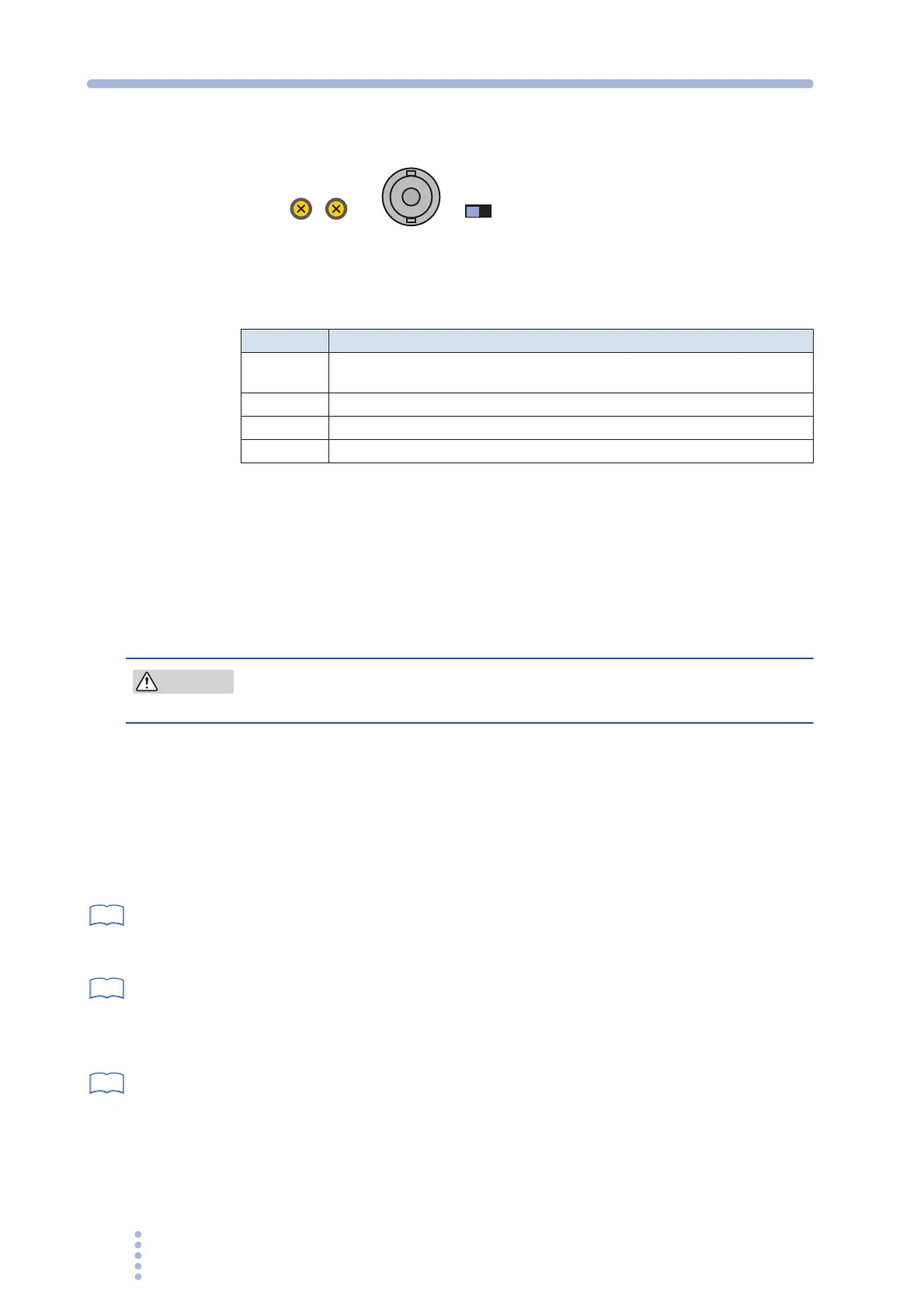
Names and functions of the parts of the analog interface board
Fig.3-15 Input terminal section
Table 3-16 Names and functions
Varying the voltage of the output AC waveform using DC signals
(EXT-AC mode)
The PCR-M outputs AC voltage ranging from 0 V to 135 V (when 135 V range is
selected) or 0 V to 270 V (when 270 V range is selected) with respect to a DC signal
input ranging from 0 V to ±10 V.
• You have to set the ATT switch to ON. Otherwise the load can be
damaged because of PCR500M output an excessive voltage to it.
1.
Check that the POWER switch is turned off.
2.
Turn the ATT switch on.
The allowable input DC voltage range is -10 V to +10 V.
3.
Connect an external signal (generator) to the INPUT terminal.
4.
Turn the POWER switch on.
page 36
5.
Press the AC/DC/EXT key (SHIFT+V) to set the OUTPUT mode to
EXT-AC.
The EXT and AC LEDs illuminate.
page 37
6.
Press the RANGE key (SHIFT+I) to set the voltage range (135 V or 270
V).
The LED corresponding to the voltage range illuminates.
AUTO cannot be selected.
page 39
7.
Press the F key to set the frequency (40 Hz to 500 Hz).
8.
Apply an external signal to the INPUT terminal.
9.
Turn the OUTPUT on.
Name Description
INPUT
BNC terminal for applying the external signal
Input terminals is electrically isolated from the output terminals of the PCR-M.
AT T Input attenuator switch
GAIN Variable resistor for fine adjusting the gain (voltage amplification ratio)
OFFSET Variable resistor for fine adjusting the offset
GAIN
OFFSET
INPUT
ATT
OFFON
CAUTION
See
See
See