36 PCR-M
Chapter 3 Operation
3.1 Switching the Output Mode
page 40, 57
The output mode can be switched between AC mode and DC mode when the
OUTPUT is turned off. If an optional interface board is installed in the option slot
on the PCR-M rear panel, EXT mode (analog interface board only) and AC+DC
mode can also be selected.
The AC/DC/EXT key is disabled when the OUTPUT is turned on.
page 84
AC+DC mode can be selected only during remote control. For details, see the
Communication Interface Manual.
Table 3-1 Output mode
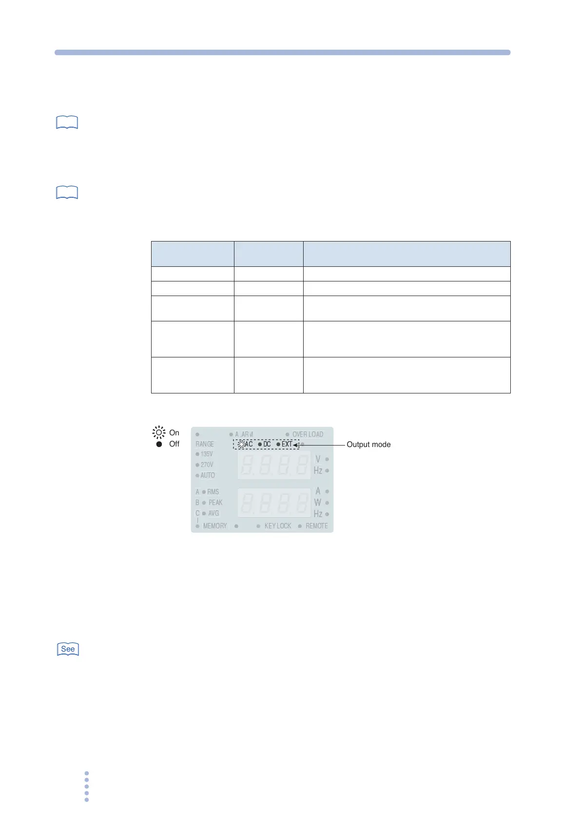
Fig.3-1 Output mode display
1.
Press the OUTPUT key to turn the OUTPUT off.
The LED above on the left of the OUTPUT key turns off.
2.
Press the AC/DC/EXT key (SHIFT+V) to select the output mode.
The mode switches between AC and DC each time the key is pressed.
page 57
The mode switches among AC, DC, EXT-AC, and EXT-DC when the analog interface
board is installed.
The output mode LEDs illuminate according to the mode as shown in Table 3-1.
See
See
Output Mode
LEDs That
Illuminate
Description
AC mode AC AC output
DC mode DC DC output
EXT-AC mode AC and EXT
Output sine waves using external DC signals
(only when the analog option board is installed)
EXT-DC mode DC and EXT
Simply amplify and output the waveform applied
externally
(only when the analog option board is installed)
AC+DC mode AC and DC
Superimpose DC voltage on the AC voltage and
output.
(only when the optional interface board is installed)
V
PEAK
135V
270V
RANGE
W
A
AVG
RMS
AUTO
MEMORY
REMOTE
KEY LOCK
A
B
C
OVER LOAD
AC
DC
EXT
On
Off
Output mode
See