6-42 Applied Operation PLZ-4W
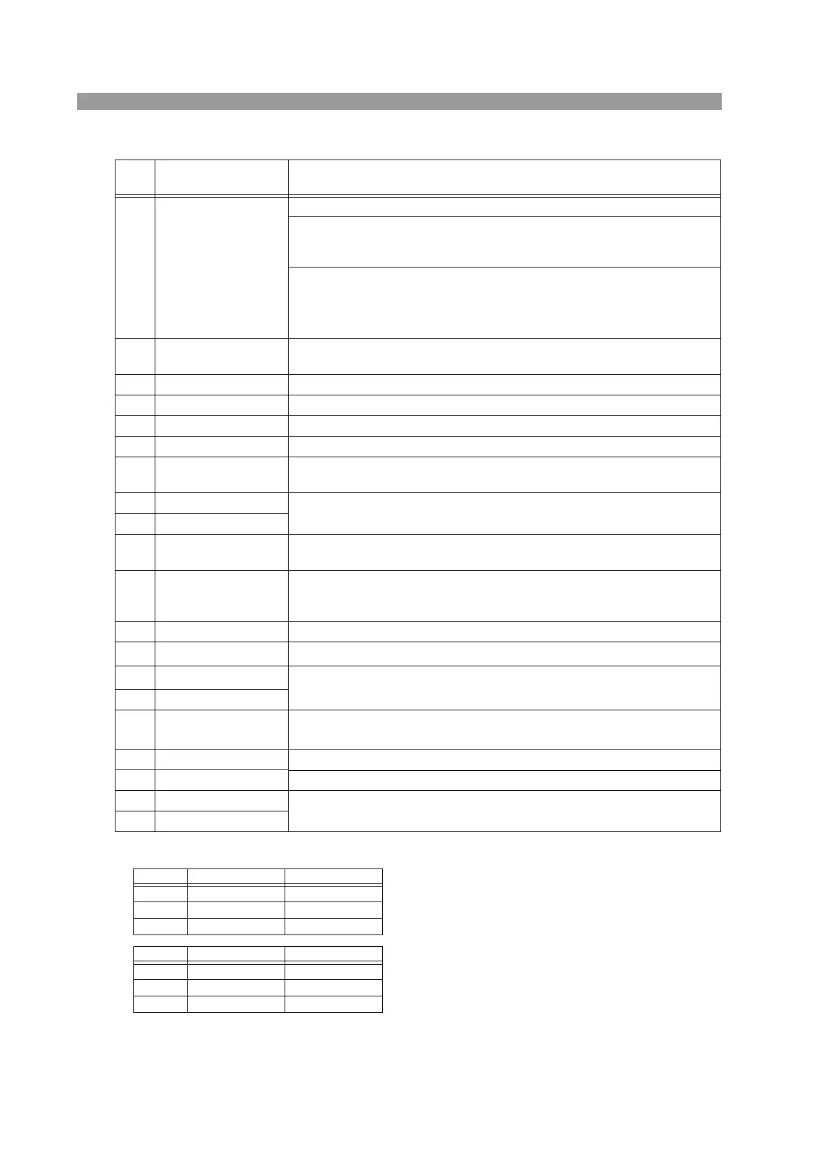
Table6-9 J1 connector pin arrangement
*1. Valid only when the front panel settings is H range.
*2.
*3.
*4. The maximum applied voltage of the photocoupler is 30 V; the maximum current is 8 mA.
Pin
No.
Signal name Description
1 EXT R/V CONT Can be used in CC, CR, CV, and CP modes
0 V to 10 V correspond to 0 % to 100 % of the rated current (CC mode), rated voltage
(CV mode), or rated power (CP mode).
0 V to 10 V correspond to maximum resistance to minimum resistance (CR mode)
0 to 10 k
correspond to 0 % to 100 % or 100 % to 0 % of the rated current (CC
mode), rated voltage (CV mode), or rated power (CP mode).
0
to 10 k correspond to maximum resistance to minimum resistance or minimum
resistance to maximum resistance (CR mode)
2 IMON Current monitor output
10 V f.s (H/L range) and 1 V f.s (M range)
3 A COM Connected to the negative load input terminal on the rear panel.
4 SUM I MON Used during master/slave operation. Connected to SUM I MON of the J2 connector.
5 PRL IN+ Used during master/slave operation. Connected to PRL OUT+ of the J2 connector.
6 PRL IN- Used during master/slave operation. Connected to PRL OUT- of the J2 connector.
7 LOAD ON/OFF CONT Turns on the load with low (or high) TTL level signal
Pulled up the internal circuit to 5 V using 10 k.
8 RANGE CONT 1
External range switch input
*1 *2
Pulled up the internal circuit to 5 V using 10 k.
9 RANGE CONT 0
10 ALARM INPUT Activates alarm with low TTL level signal input.
Pulled up the internal circuit to 5 V using 10 k.
11 TRIG INPUT When paused, clears the pause when a high level TTL signal is applied for 10 s or
longer.
Pulled down the internal circuit to A COM using 100 k.
12 A COM Connected to the negative load input terminal on the rear panel.
13 LOAD ON STATUS
Turns on when load is on. Open collector output by a photocoupler.
*4
14 RANGE STATUS 1
Range status output. Open collector output by a photocoupler.
*4
15 RANGE STATUS 0
16 ALARM STATUS Turns on when an alarm (OVP, OCP, OPP, OHP, REV, or UVP) is activated or when an
external alarm is applied. Open collector output by a photocoupler.
*4
17 STATUS COM STATUS signal common for pins 13 to 16.
18 N.C.
19 SHORT SIGNAL OUT Relay contact output (30 VDC/1 A)
20 SHORT SIGNAL OUT
RANGE CONT 0 RANGE CONT 1
H range 1 1
M range 1 0
L range 0 1
RANGE STATUS 0 RANGE STATUS 1
H range OFF OFF
M range OFF ON
L range ON OFF



 To Next Page