PLZ-4W Applied Operation 6-63
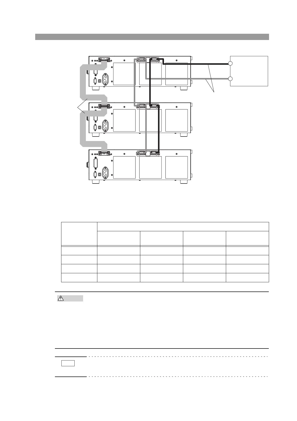
Fig. 6-49 Parallel connection of two slave units
Table 6-13 shows the relationship between the number of slave units and the capacity.
Table 6-13 The number of units connected in parallel and the capacity
• When carrying out parallel operation, be sure to use the load input termi-
nal on the rear panel. Do not connect other equipment to the load input ter-
minal on the front panel.
• Improper connection of the J1 and J2 connectors can damage the PLZ-4W.
• Use the shortest load wire and flat cable possible for the connection. Use a
load wire of sufficient thickness by taking into account the current being used.
It is recommended to use the bus bar instead of wiring the cable.
• Separate the load cable from the flat cable as much as possible to prevent unstable
operation.
Slave unit
Maximum current/Maximum power
PLZ164W
/164WA
PLZ334W PLZ664WA PLZ1004W
1 unit 66 A / 330 W 132 A / 660 W 264 A / 1 320 W 400 A / 2 000 W
2 units 99 A / 495 W 198 A / 990 W 396 A / 1 980 W 600 A / 3 000 W
3 units 132 A / 660 W 264 A / 1 320 W 528 A / 2 640 W 800 A / 4 000 W
4 units 165 A / 825 W 330 A / 1 650 W 660 A / 3 300 W 1 000 A / 5 000 W
J1
J2
DC INPUT
1000W
1.5
-
150V
0
-
200A
J1
J2
DC INPUT
1000W
1.5
-
150V
0
-
200A
J1
J2
DC INPUT
1000W
1.5
-
150V
0
-
200A
Equipment
under test
Master unit
Slave unit 1
Slave unit 2
J2
J2
J1
J1
–
+
+
–
+
–
–
+