PLZ-4W Maintenance and Calibration 8-11
CV mode calibration (calibration number 4 and 5)
Carry out calibration on the 15-V range items first according to steps E to H. Then,
carry out calibration on the 150-V range items.
The shunt resistor is not used, but you can leave it connected.
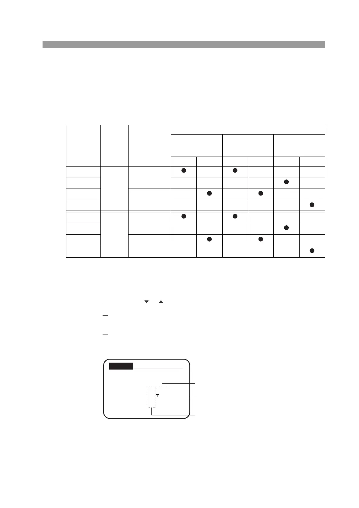
Table 8-4 Overview of the procedure
■ Low range calibration
Step E: Calibration of the offsets of internal reference voltage for out-
put setting and measured value
1.
Press the or CURSOR key to select the calibration number “4. CV 15 V”.
2. Connect a CC power supply to the load input terminal and supply 0.3 A.
Set the voltage of the power supply to 15.5 V or greater.
3.
Press the ENTER key.
The load automatically turns on, and the offset calibration (CV 15 V Offset
Adjustment) screen appears.
Fig. 8-8 CV 15 V Offset Adjustment screen
Procedure
Voltage
range
Percentage with
respect to the full
scale (%)
Calibration item
Internal reference
voltage for output
setting
Measured value
Internal reference
voltage for protection
function setting
Offset Gain Offset Gain Offset Gain
E
15V
10
––––
F –––– –
G
100
––––
H –––––
E
150V
10
––––
F –––– –
G
100
––––
H –––––
Offset Adjustment
PREV NEXT
DAC REF :
0x0001
MON :
0x0001
CV 15V
Cursor
Indicates hexadecimal.
Displays the current
calibration value
(hexadecimal) first.
 Loading...