8-10 Maintenance and Calibration PLZ-4W
Step D: Calibration of the gain of the internal reference voltage for
protection function setting
12.
Press the ENTER key.
The gain calibration (CC (Low) Limit Gain Adjust) screen appears.
13.
Press the or CURSOR key to select DAC LIM, and turn the rotary
knob. Set the current flowing through the shunt resistor within 0.1 % of
the value corresponding to 100 % of the range full scale.
See Table 8-3 for the current settings of each model.
14.
Press the ENTER key.
The load is automatically turned off.
The calibration of the low range current is complete.
■ Mid range calibration
15. Return to number 1 of step A and calibrate the mid range (calibration
number “2. CC (Mid)”) by carrying out a similar procedure.
■ High range calibration
16. Return to number 1 of step A again and calibrate the High range (cali-
bration number “3. CC (High”) by carrying out a similar procedure.
Step 16 completes the CC mode calibration.
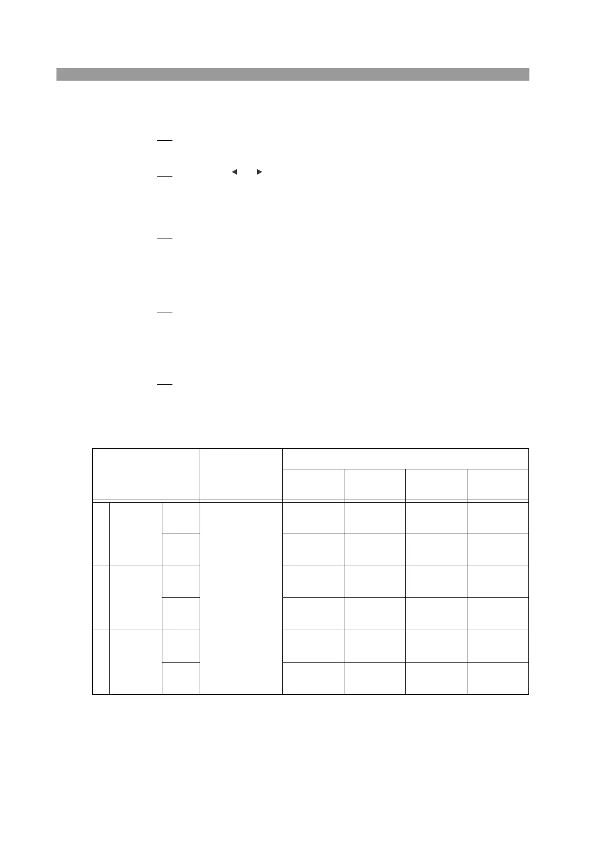
Table 8-3 CC mode settings
Calibration number
and item
Output setting of
the power supply
Current to be matched
PLZ164W
PLZ164WA
PLZ334W PLZ664WA PLZ1004W
1CC(Low)
Offset
Voltage: 5 V
Current:
Rated current of
the load device
33 mA
0.033 mA
66 mA
0.066 mA
132 mA
0.13 mA
200 mA
0.20 mA
Gain
330 mA
0.33 mA
660 mA
0.66 mA
1.32 A
0.013 A
2.00 A
0.020A
2CC(Mid)
Offset
330 mA
0.33 mA
660 mA
0.66 mA
1.32 A
0.013 A
2.00 A
0.020A
Gain
3.3 A
0.0033 A
6.6 A
0.0066 A
13.2 A
0.013 A
20.0 A
0.020 A
3 CC(High)
Offset
3.3 A
0.0033 A
6.6 A
0.0066 A
13.2 A
0.013 A
20.0 A
0.020 A
Gain
33.0 A
0.033 A
66.0 A
0.066 A
132.0 A
0.132 A
200.0 A
0.200 A
 Loading...