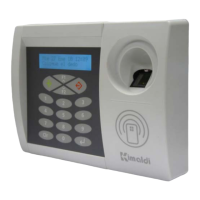
BioMax2 / KBio2-Online
Installation and Programming Manual
www.kimaldi.com Page 11 of 91
J5: Ethernet Connector (RJ45 connection)
J9 - TTL_0 connector to Card Reader: NdCAN-compatible
Pin 1 - Data Signal (TTL_0)
Pin 2 - Clock Signal (TTL_0)
Pin 3 - CLS Signal (TTL_0)
Pin 4 - +5 VDC Output
Pin 5 - Negative power supply pole (GND)
J7: Connection to FIM biometric identification module or to generic RS-232 reader
Pin 1 - +5 VDC Output
Pin 2 - UART_1 - Tx 232 signal to reader or FIM Module
Pin 3 - UART_1 - Rx 232 signal to reader or FIM Module
Pin 4 - Power supply negative pole (GND)
J8: JST Connector to Kimaldi Optical Barrier
Pin 1 - Anode (+) of the emitting LED
Pin 2 - Cathode (-) of the emitting LED
Pin 3 - Collector (+) of the receiving phototransistor
Pin 4 - Emitter (GND) of the receiving phototransistor
P2: Display Contrast: adjustment potentiometer
JP1, JP2: Jumpers to select KSP Application_ID (see Subsection 6.3.2. )
LEDs showing the electronics status:
LD1 - 3V3 supply operating
LD2 - Rx/Tx Instructions or Events between BioMax2 and the Host computer
LD3 - Red - Ethernet Link Error
LD4 - Green - Ethernet Activity (when blinking).
In addition, Keypad and Display connections are available for the OEM version of the
equipment:
J6: 4x4 Keypad connector
Pin 1 - Column 3 (OUT) Pin 5 - Row 0 (IN)
Pin 2 - Column 2 (OUT) Pin 6 - Row 1 (IN)
Pin 3 - Column 1 (OUT) Pin 7 - Row 2 (IN)
Pin 4 - Column 0 (OUT) Pin 8 - Row 3 (IN)
J10: Connector to 20x2 Display, with incorporated Backlit
J14 - Connector/socket for KiWi2 Converter (UART0):
Pin 1 - No Connect
Pin 2 - No Connect
Pin 3 - UART_0 - Tx 232 signal to Host
Pin 4 - UART_0 - Rx 232 signal to Host