BioMax2 / KBio2-Online
Installation and Programming Manual
www.kimaldi.com Page 9 of 91
4. Installation
4.1.
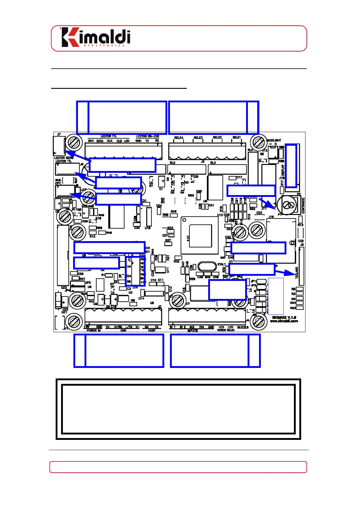
Connector signals, BioMax2
WARNING !!!!
Take the necessary antistatic precautions when handling this product
to avoid damaging the sensitive electronic devices.
BioMax2 electronics board requires +5 Vdc supply
1 2 3 4 5 6 7 8 1 2 3 4 5 6 7 8
8 7 6 5 4 3 2 1 8 7 6 5 4 3 2 1
J3
5 vcc
GND
N.C.
N.C.
N.C.
N.C.
Host Rx
Host Tx
J4
DIN_0
DIN_1
DIN_2
DIN_3
GND
LED_0 (+)
LED_1 (+)
BUZZER (-)
J2
RELE 3-A
RELE 3-B
RELE 2-A
RELE 2-B
RELE 1-A
RELE 1-B
RELE 0-A
RELE 0-B
J1
GND
DATA_1
CLK_1
CLS_1
+5V Out
GND
Lector Tx
Lector Rx
P2: Contrast
J6: Keypad
J5: Ethernet
J9: TTL-0
J7: FIM Connector
J8: Opt. Bar.
J10: Display
J14: KiWi2
JP1, JP2
LEDs
JP1
JP2
LD1
LD2
LD3
LD4
J15: BiomaxPlus-DB