Assembly, Installation and Putting Into Operation
4.4.3 Digital Control
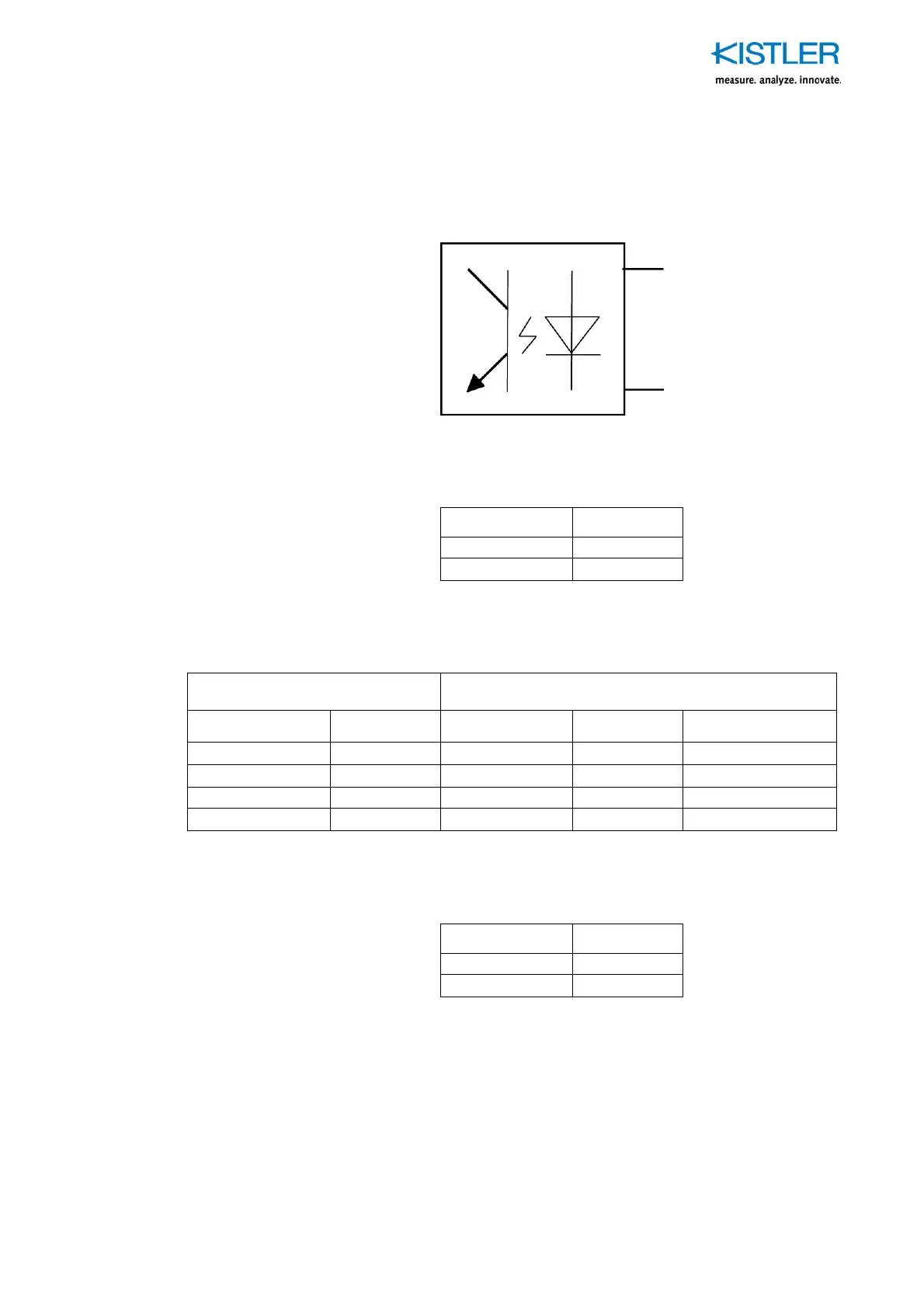
All Digital Inputs are isolated with Opto Couplers:
Dig input
Control GND
Fig. 10:
Digital Control input circuit
Logical signal Dig. input
0 <4,4 V
1 5 ... 45 V
Table 1: Digital Control input signals
Range select group I F
x
, F
y
(Shear) Range select group II F
z
(Vertical)
B (pin 17) A (pin 16) B' (pin 18) A' (pin 13)
0 0
0 0 Range 4 (biggest)
0 1
0 1 Range 3
1 0
1 0 Range 2
1 1
1 1 Range 1 (smallest)
Table 2: Range selection
Operate (pin 6) Dig. Input
1 Operate
0 Reset
Table 3: Operate/Reset
9287C
_002-462e-03.11 Page 19