Section 2
Installation
20479262
9-2010/Rev 02
2-4
Table 2-2
Ampacity and Power Voltage Requirements
Power Voltage
Motor
Horsepower
Full Load
Amps
Circuit Breaker
Amps
400/3/50 50 66 100
415/3/50 50 64 100
460/3/60 50 58 80
575/3/60 50 52 70
2.5 Service Connections
Depending on the model, the intensifier requires one or two incoming water sources, cooling
water and cutting water; one or two drain lines, cooling water and wastewater; a high pressure
discharge line, and an air supply line. All piping must comply with local, regional and national
codes.
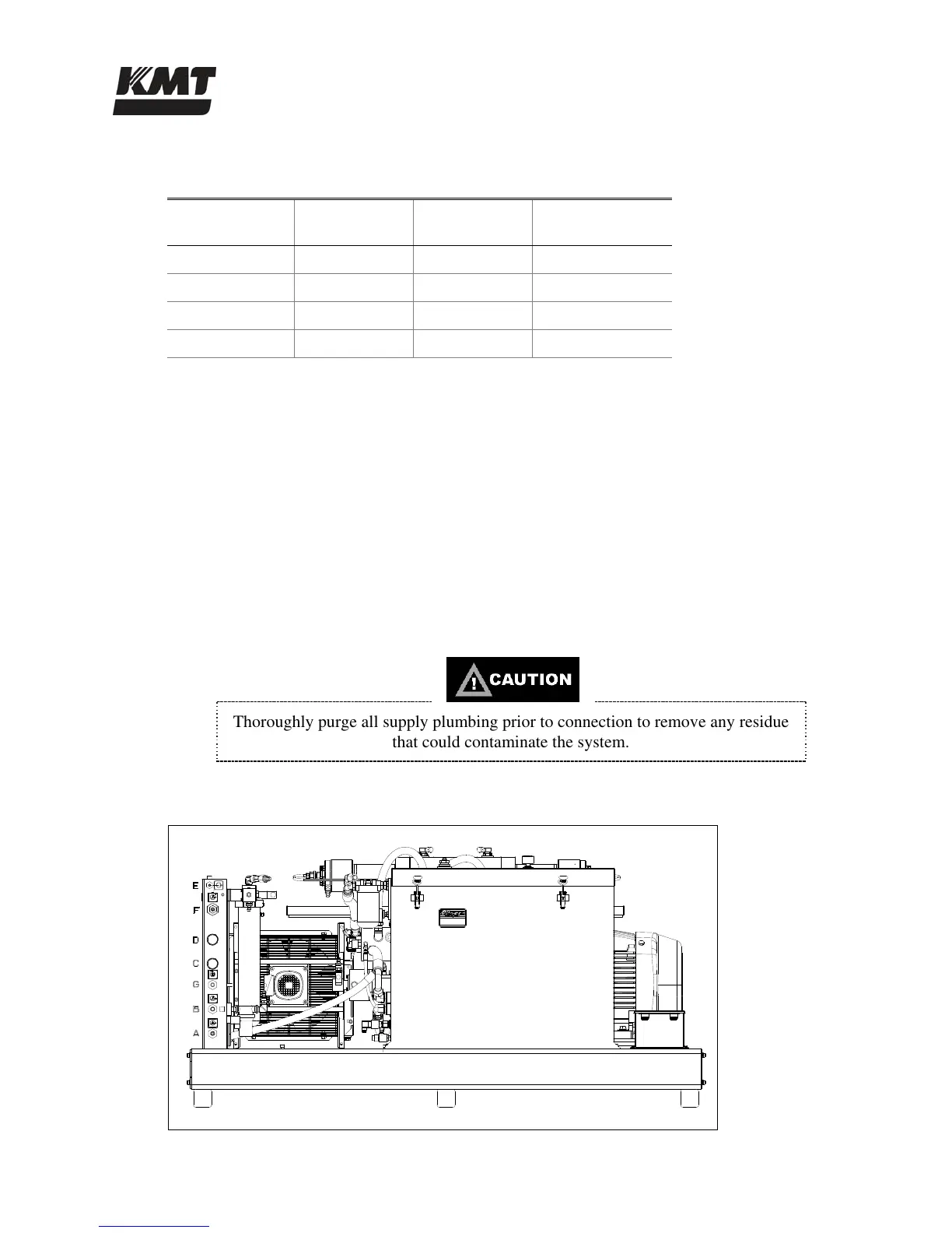
All service connections are made on the bulkhead of the machine as shown in Figure 2-3, Service
Connections. Table 2-3 lists the fittings required for each interface connection.
With the exception of the wastewater drain line, manual shutoff valves should be installed for all
connections. To facilitate service, the valves should be located as close as practical to the
interface connection.
Thoroughly purge all supply plumbing prior to connection to remove any residue
that could contaminate the system.
Figure 2-3: Service Connections
 Loading...