20479291
2-2012/Rev 04
8-1
SECTION 8
HIGH PRESSURE WATER SYSTEM
8.1 Overview
The high pressure water system is supported by both the cutting water supply circuit and the
hydraulic circuit. Cutting water of sufficient flow and pressure is routed from the cutting water
supply circuit to the intensifier where it is pressurized up to 60,000 psi (4,137 bar) and delivered
to the cutting head.
The directional control valve in the hydraulic system creates the stroking action of the intensifier
by sending pressurized hydraulic oil to one side of the hydraulic cylinder or the other. As the
flow is sent to one side, hydraulic fluid is returned to the reservoir from the opposite side.
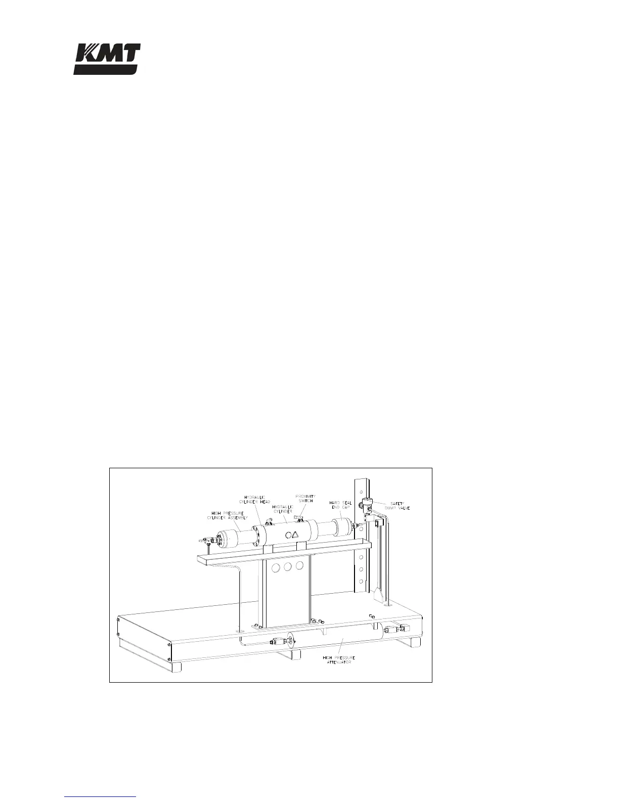
System components include a double-ended hydraulic cylinder; reciprocating piston assembly;
high pressure cylinder assemblies attached to each end of the hydraulic cylinder; two plungers,
sealing heads and hard seal end caps; one liter capacity attenuator, and a safety dump valve.
Sophisticated check valves and seal assemblies ensure hydraulic oil, and the low pressure and
high pressure water travel in the appropriate direction.
8.2 Operation
The directional control valve sends pressurized hydraulic oil to one side of the hydraulic cylinder.
The pressurized oil pushes against the piston, moving it in one direction until it activates the
proximity switch at the end of the stroke. The hydraulic flow is then sent to the opposite side of
the cylinder, and the piston reverses direction until it activates the proximity switch at the
opposite end of the stroke.
Figure 8-1: High Pressure Water System
 Loading...