20479287
1-2009/Rev 0
7-1
SECTION 7
ELECTRICAL SYSTEM
7.1 Overview
Major components of the electrical system for the S50 include the electric motor, the wiring
harness that connects the sensors and solenoid valves to the customer supplied controller and, if
applicable, wiring for the fan motor.
The 12-lead electric motor can be wired for either wye-delta or across-the-line starting.
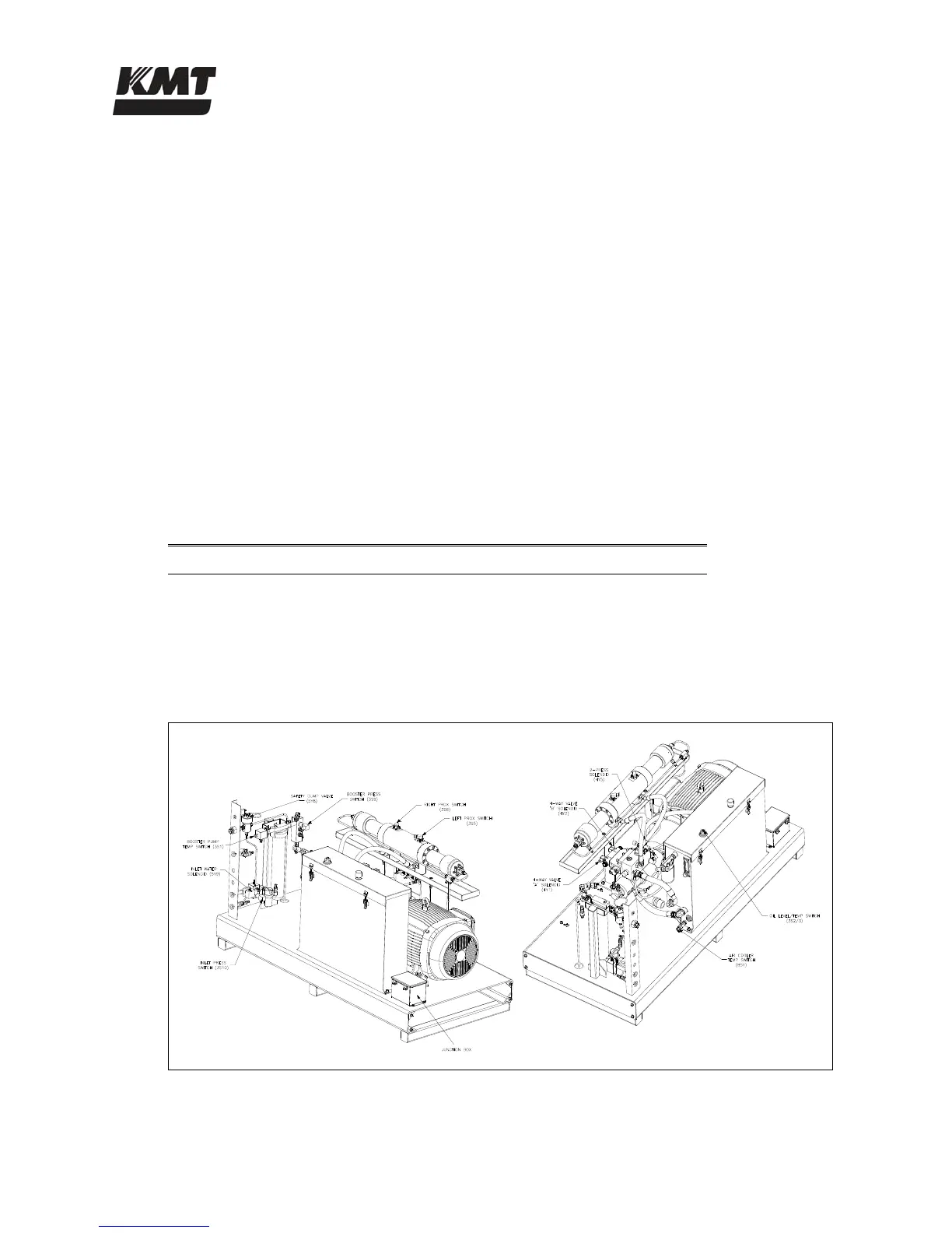
7.2 Sensors and Solenoids
Sensors monitor operating conditions and electronically operated solenoids provide basic
intensifier shift control. The cables connected to these sensors and solenoids are bundled into a
wiring harness. Table 7-1 lists the shutdown settings.
Table 7-1
Shutdown Settings
Label Sensor Shutdown Setting
3S2/3 Low hydraulic oil level 30 gal (114 L)
3S2/3 High hydraulic oil temperature
144 F (62 C)
3S1 Booster pump overheat
128 F (53 C)
Figure 7-1: Sensors and Solenoids
 Loading...