Section 7
Electrical System
20479287
1-2009/Rev 0
7-5
7.3 Service and Maintenance Procedures
Electrical components require minimal service. The proximity switches on the hydraulic cylinder
may require replacement.
NOTE
Refer to Section 11, Parts List for a complete listing of replacement parts and part
numbers.
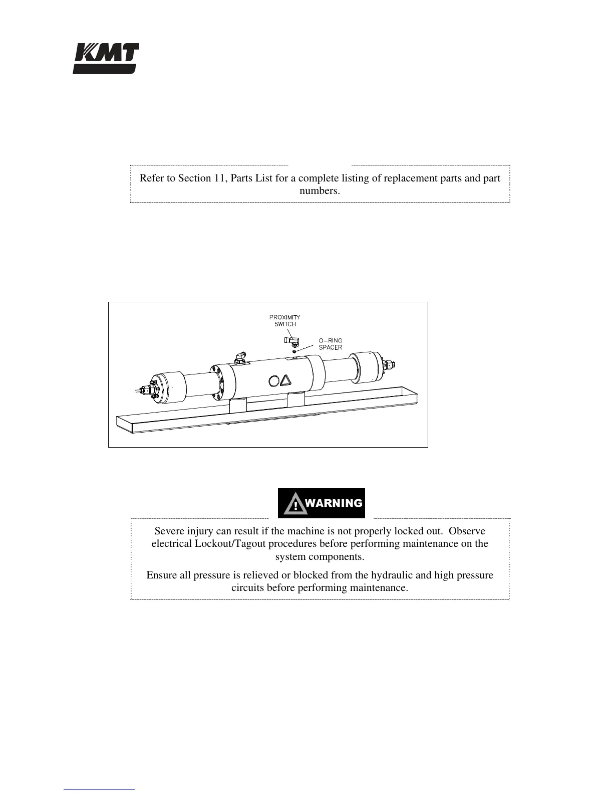
Proximity Switch Maintenance
A proximity switch has failed and needs to be replaced if the LEDs do not change state,
indicating they are not sensing the piston, if an LED flashes continuously.
Figure 7-2: Proximity Switch
1. Turn the machine off and observe the appropriate Lockout/Tagout procedures.
Severe injury can result if the machine is not properly locked out. Observe
electrical Lockout/Tagout procedures before performing maintenance on the
system components.
Ensure all pressure is relieved or blocked from the hydraulic and high pressure
circuits before performing maintenance.
2. Remove the electrical cable from the failed proximity switch.
3. Remove the two socket head screws, the failed switch and the o-ring spacer.
4. Install a new proximity switch by positioning the o-ring spacer and the switch. Ensure the
o-rings are correctly oriented.
5. Apply JL-M grease to the threads on the screws and tighten to 140-160 in-lbs (16-18 Nm).
 Loading...