Section 7
Electrical System
20479287
1-2009/Rev 0
7-4
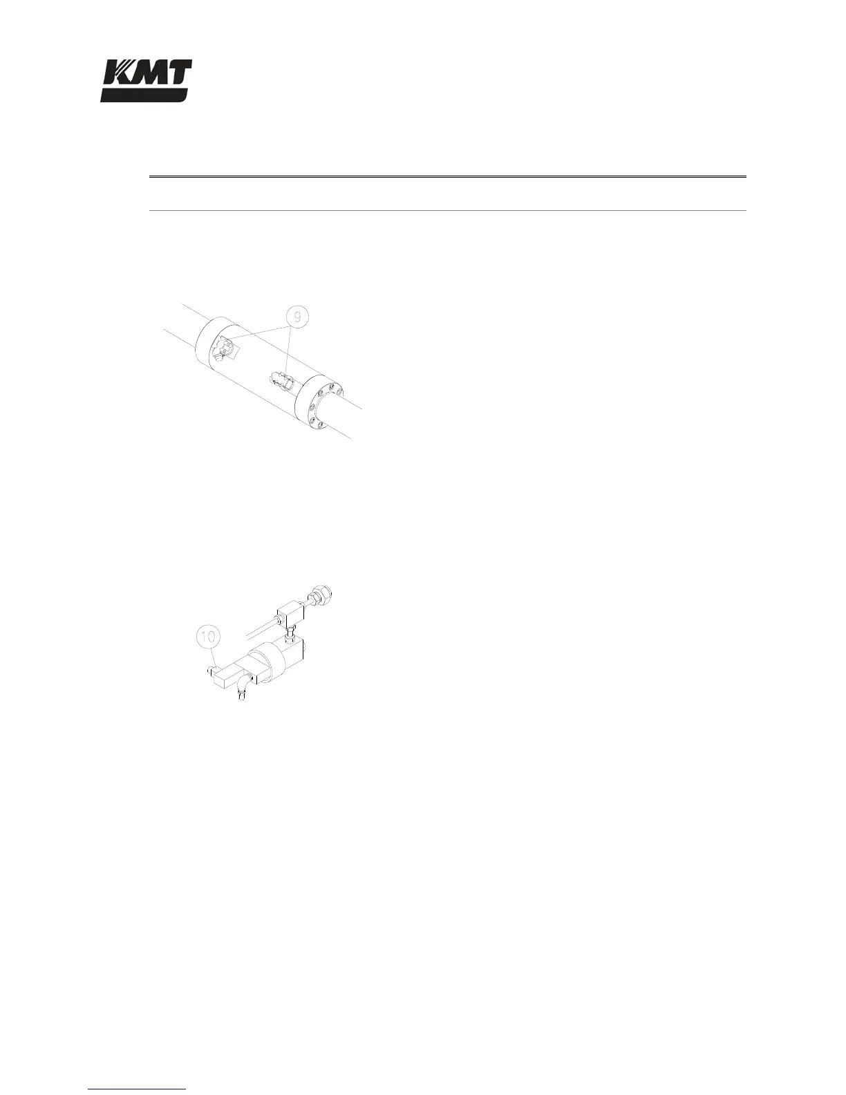
Table 7-2
Sensors and Solenoids
Component Function
Hydraulic Cylinder
9 As pressurized hydraulic oil is sent to one side of the
hydraulic cylinder, it pushes against the piston,
moving it in one direction until it activates the
proximity switch at the end of the stroke. The
hydraulic flow is then sent to the opposite side of the
cylinder, and the piston reverses direction until it
activates the proximity switch at the opposite end of
the stroke.
The green light on the proximity switch indicates
there is power to the switch. The light turns red
when the switch is activated. The proximity
switches are magnetically activated by the presence
of the metallic surface of the piston. When the
switch is activated, it sends a signal to the PLC to
change the flow of the directional control valve and
reverse direction.
High Pressure Safety Dump Valve
10 When control power is removed, the safety dump
valve releases the stored pressure in the intensifier
and high pressure delivery lines. The high pressure
dump valve assembly includes a normally open high
pressure water valve and a solenoid operated air
valve.
The normally open pneumatic dump valve is held
closed by air pressure. When the air supply is
interrupted from an emergency stop, the valve opens
and allows water to flow through the valve. Pressure
is released in the intensifier and the high pressure
water stream exits through the drain.
 Loading...