Section 2
Installation
20479262
9-2010/Rev 02
2-7
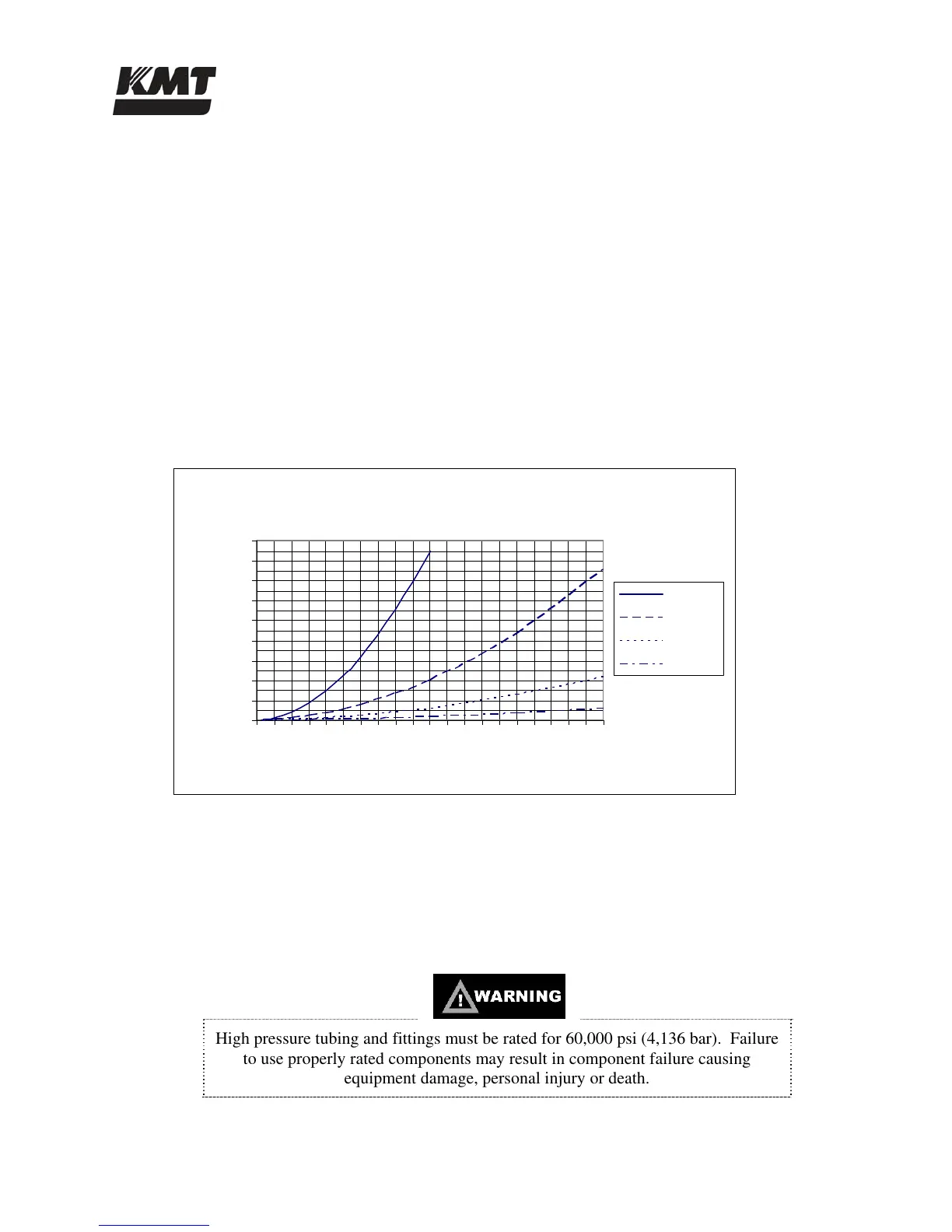
2.6 Flow Requirements
Figure 2-4, Pressure Drop Values, illustrates the pressure drop for four different pipe sizes. The
graph can be used to calculate the minimum source water pressure.
1. Enter the graph at the required GPM and note the pressure drop figures for the different
pipe sizes.
2. Multiply the pressure drop (PSI/FT) by the length in feet of each pipe size used from the
water source to the intensifier. Add the values together for a total pressure drop value.
3. Add 30 to the total pressure drop to determine the minimum flowing, source water
pressure required to provide adequate supply to the intensifier.
Cutting water and cooling water capacity should be calculated separately. Note that the cutting
water requirements represent instantaneous, not average, demand. The machine will not start if
the inlet cutting water pressure drops below 30 psi (2 bar).
Figure 2-4: Pressure Drop Values
2.7 High Pressure Piping
High pressure piping is used to transport high pressure cutting water from the machine to the
cutting station. High pressure piping and fittings must be properly rated and sized. When
transporting high pressure water over long distances, tubing and fittings with an outside diameter
of 9/16-inch are recommended. The large tubing size reduces vibration, strain and motion; as
well as reducing pressure drop and pulsation.
High pressure tubing and fittings must be rated for 60,000 psi (4,136 bar). Failure
to use properly rated components may result in component failure causing
equipment damage, personal injury or death.
Pipe Sizing
0
0.05
0.1
0.15
0.2
0.25
0.3
0.35
0.4
0.45
0 1 2 3 4 5 6 7 8 9 10 11 12 13 14 15 16 17 18 19 20
Required GPM
Pressure drop (PSI/FT
1/2" ID
3/4" ID
1" ID
1-1/4" ID
 Loading...