Section 2
Installation
20479262
9-2010/Rev 02
2-9
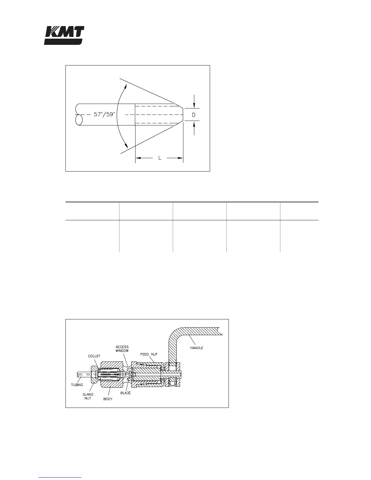
Figure 2-6: Cone and Thread Dimensions
Table 2-8
Cone and Thread Dimensions
Tube OD
Tube ID
D
(Maximum)
L
(Maximum)
Thread
UNF-LH
1/4” (6.35 mm) 0.083” (2.11 mm) 0.125” (3.2 mm) 0.562” (14.3 mm) 1/4” - 28
3/8” (9.52 mm) 0.125” (3.18 mm 0.219” (5.6 mm) 0.750” (19.1 mm) 3/8” - 24
9/16” (14.29 mm) 0.188” (4.78 mm) 0.281” (7.1 mm) 0.938” (23.8 mm) 9/16” - 18
Hand Coning
1. Place the body of the coning tool in a vise allowing adequate clearance for the rotation of
the cutter handle. Position the tool so the cutter handle is elevated slightly so the lubricant
will flow to the cutting blade.
Figure 2-7: Hand Coning Tool
2. Turn the feed nut counter-clockwise to retract the cutting blade past the access window.
 Loading...