Section 8
High Pressure Water System
20479291
2-2012/Rev 04
8-23
10. Install the high pressure cylinder assembly into the hydraulic cylinder head, following the
procedure, High Pressure Cylinder Assembly Installation.
11. Connect the high and low pressure water piping and turn the low pressure water supply
on.
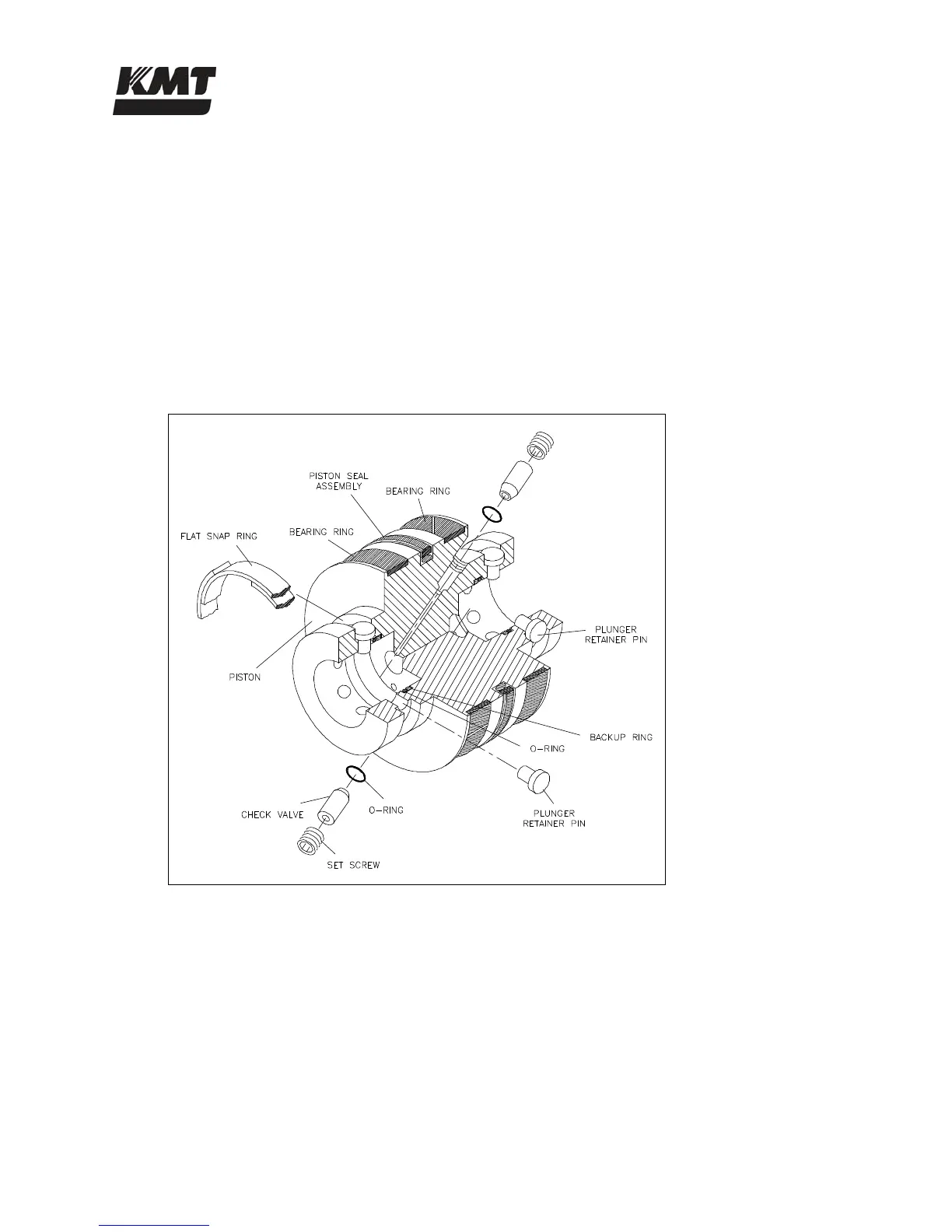
8.11 Hydraulic Piston
Two bearing rings provide wear contact between the piston and the inside diameter of the
hydraulic cylinder. On each end of the piston, six retainer pins hold the plunger in position. The
plunger retainer pins are held in place by a flat snap ring. Two internal check valves vent
unwanted hydraulic pressure from one side of the piston to the other, preventing pressure from
building behind the plunger button.
Figure 8-19: Hydraulic Piston Components
Hydraulic Piston Removal
The following procedure is used to remove the hydraulic piston.
1. Turn the machine off and observe the appropriate Lockout/Tagout procedures.
 Loading...