Section 7
Electrical System
20479287
1-2009/Rev 0
7-2
Table 7-2
Sensors and Solenoids
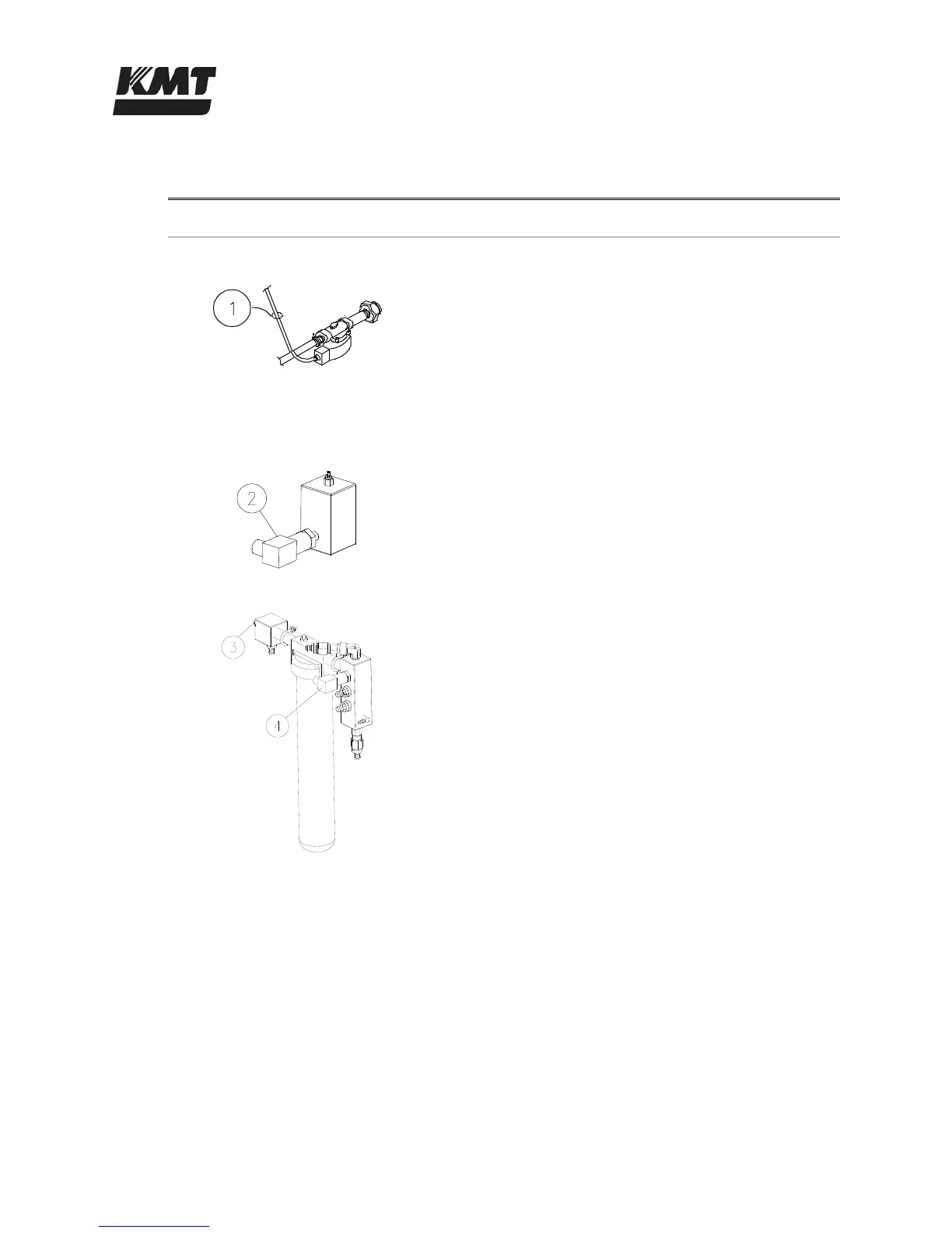
Component Function
Inlet Water Solenoid Valve
1 The normally closed, inlet water solenoid valve is
located at the service bulkhead. When the control
power is turned on, the valve opens and allows low
pressure cutting water to enter.
Low Pressure Water Filter Assembly
2 The 30 psi pressure switch, mounted on the inlet
manifold, monitors the inlet cutting water to protect
the booster pump from damage due to insufficient
water supply pressure.
3 A temperature switch monitors the temperature of
the cutting water from the booster pump. The
temperature switch prevents booster pump
overheating due to lack of water, long deadhead
conditions or a blocked orifice.
4 To ensure adequate water pressure and supply to the
intensifiers, the discharge pressure is monitored by a
60 psi pressure switch.
 Loading...