Section 8
High Pressure Water System
20479291
2-2012/Rev 04
8-14
3. Use two wrenches to remove the gland nut. The poppet pin, spring and discharge poppet
will normally remain in the gland nut when it is removed. Remove the components from
the gland nut.
4. Use a magnet to remove the seat from the sealing head.
5. Inspect the poppet pin for wear and replace the pin if worn.
6. Inspect both faces of the seat for damage or cracking. A cracked or damaged seat must be
replaced. The seat can be installed with either face toward the discharge poppet. If one
face is worn, but the opposite is not, the seat can be reversed, placing the new surface
toward the poppet. A slight burr at the hole edge identifies the used side of the seat. If
both faces are worn, the seat must be replaced.
NOTE
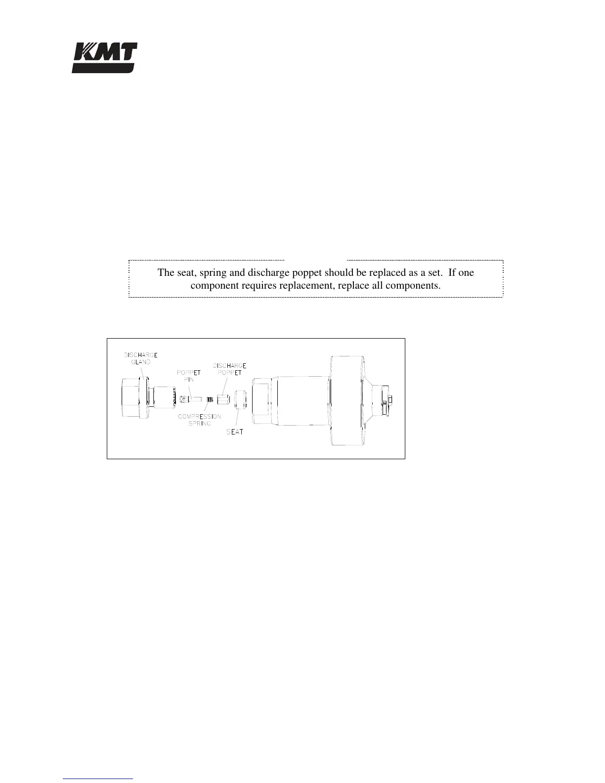
The seat, spring and discharge poppet should be replaced as a set. If one
component requires replacement, replace all components.
Figure 8-10: High Pressure Discharge Check Valve
7. Apply a thin film of Pure Goop to the face of the seat opposite the discharge poppet and
install the seat into the sealing head. If the existing seat is reused, install the seat with the
new surface facing the poppet.
8. Install the poppet pin and the spring, with the larger end of the spring facing the poppet,
and then install the poppet into the gland nut.
9. Apply Pure Goop to the sealing face and the threads on the gland nut and thread the gland
nut into the sealing head. Hand-tighten until there is a 0.20 inch (5 mm) gap between the
gland nut and the sealing head. No threads should show. If the gap exceeds 0.20 inch (5
mm), the poppet or seat has slipped out of position. The parts must be removed, inspected
and re-assembled.
10. Use a crowfoot/torque wrench combination and tighten the gland nut to the torque
specifications in Table 8-1.
 Loading...