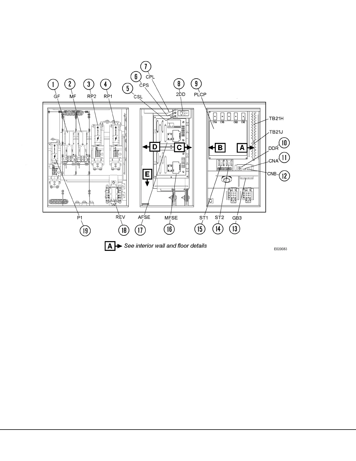
1. Alternator Field Contactor
2. Motor Field Contactor
3. Retard Power Contactor No. 2
4. Retard Power Contactor No. 1
5. Cabinet Service Light Switch
6. Control Power Switch
7. Control Power Light
8. Two Digit Display Panel
9. Propulsion Load Control Panel (FL275)
10. Diagnostic Data Reader Connector
11. Statex Channel A (PTU) Connector
12. Statex Channel B Connector
13. Ground Bus No. 3
14. Synchronizing Transformer No. 2
15. Synchronizing Transformer No. 1
16. Motor Field Static Exciter
17. Alternator Field Static Exciter
18. Reverser
19. Propulsion Contactor No. 1