J06020 Rockwell Armature Speed Rear Disc Brakes J6-9
1. Normally, piston assembly will be removed from
brake assembly with return pin in an extended
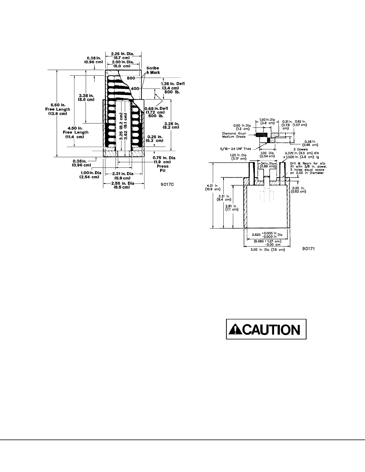
position. Set calibrated spring pod (Figure 6-9) on
table of arbor press, place piston assembly on top
of spring pod and apply arbor force slowly to
return pin to retracted position. Pin should slip
between 400-800 lb. (1779-3558 N) scribed
marks on spring pod.
2. If slippage definitely occurs before the 400 lbs.
(1779 N) mark on spring pod, grips and return pin
should be replaced. Slippage above the 800 lb.
(3558 N) limit is unlikely, but if this occurs return
pin and grip assembly should be removed and
inspected for grip slippage, and return pin exam-
ined for damage. If slippage of return pin and grip
assemblies are over 800 lb. (3558 N), pins and
grip should also be replaced.
3. Return pin should be placed in extended position
when assembling into brake caliper for a special
pin retraction tool (Figure 6-10) or equivalent, is
required for this. Insert piston assembly in tool
and secure firmly with knurled nut. Place pin
return tool/piston assembly combination on arbor
press table, drop in 3 dowel pins as indicated,
place spring pod tool on top of dowels, apply
force slowly to top of spring pod and again
observe if grip slippage occurs within the pre-
scribed limits.
Grip Force Measurement
To measure grip force of grip assemblies installed on
return pin, it is necessary to have available either a
force calibrated hydraulic press, or a calibrated spring
pod (Figure 6-9) used with a standard arbor press.
Do not use spring checker for making grip force
measurements. Sudden grip force release can
destroy calibration and possibly result in damage
to checker.
1. Place spring pod on arbor press table, use
sleeves A & B (Figure 6-6) as illustrated in Figure
6-11 to move grips back and forth several times
on return pin.
2. Apply force slowly, observe that slippage occurs
between the 400 (1779 N) and 800 lb. (3558 N)
markings on spring pod.
FIGURE 6-9. CALIBRATED SPRING POD
NOTE: The spring for the calibrated spring pod is
from Danly Machine Corporation, Spring Part
Number 9-3218-21. If Danly spring is not
available, use an equivalent, stamping die spring,
with these specifications.
• 2.00 in. (5.08 cm) Hole Diameter
• 1.00 in. (2.54 cm) Rod Diameter
• 4.50 in. (11.43 cm) Free Length
• 590 lbs/in. (2624 N/cm) Force Required to
Deflect
FIGURE 6-10. RETURN PIN RETRACTION