L03026 7/02 Hydraulic Component Repair L3-9
15. Install the opposite pressure plate with the
bronze side down and the milled slot facing
toward the discharge side.
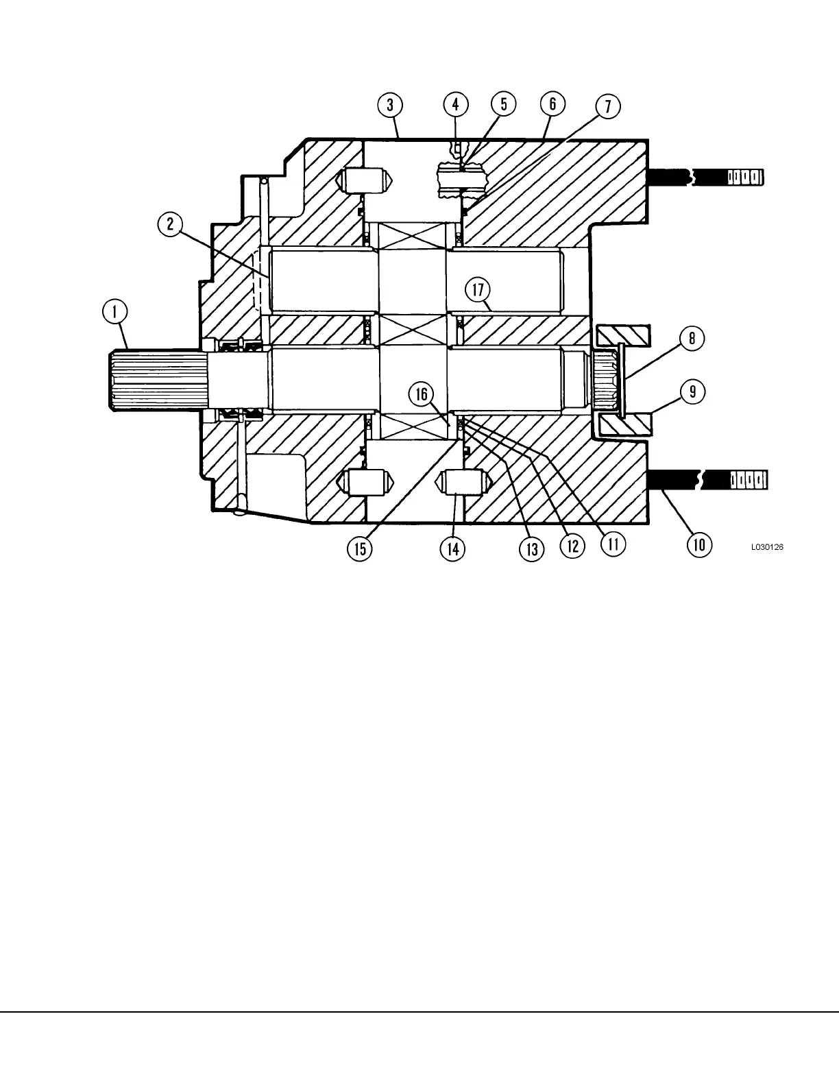
16. Install steel rings (11, Figure 3-13), backup ring
(12), O-ring and retainer (13). Install isolation
plate with its relief toward the pressure plate.
17. Lubricate and install thru stud O-rings (5) and
connector plate O-ring (7). Install dowel (14) if
removed. Lubricate the I.D. of the bearings (17)
and install connector plate (6). Install snap ring
(8) and coupling (9).
18. Lubricate O-ring (3, Figure 3-14) and install in
bearing plate (7). Lubricate O-rings (4) and
install over studs (12). Replace dowel (2) if
removed. Install bearing plate (7).
19. Repeat steps 10, 11 and 12 for installation of the
steel rings, backup ring, O-ring, retainer, isola-
tion plate and pressure plate.
20. Lubricate I.D. of bearings (18, Figure 3-14).
Install O-rings (8 & 9) and dowel (25) if
removed. Install gear plate (10). Make sure
relief in gear plate is toward bearing plate (7).
21. Install rear drive gear (1) and idler gear (13). The
rear drive gear must be timed with the front
drive gear. This is accomplished by lining up a
tooth on the rear drive gear with the valley of
two teeth on the front drive gear, as shown in
Figure 3-12.
22. Repeat steps 15 and 16 for installation of the
remaining pressure plate, steel rings, backup
ring, O-ring, and retainer and isolation plate.
FIGURE 3-13. HOIST PUMP REASSEMBLY
1. Drive Gear and Shaft
2. Idler Gear
3. Gear Plate
4. Relief
5. O-Ring
6. Connector Plate
7. O-Ring
8. Snap Ring
9. Coupling
10. Thru Studs
11. Steel Ring
12. Backup Ring
13. O-Ring & Retainer
14. Dowel
15. Isolation Plate
16. Pressure Plate
17. Bearing
 Loading...


