L3-10 Hydraulic Component Repair 7/02 L03026
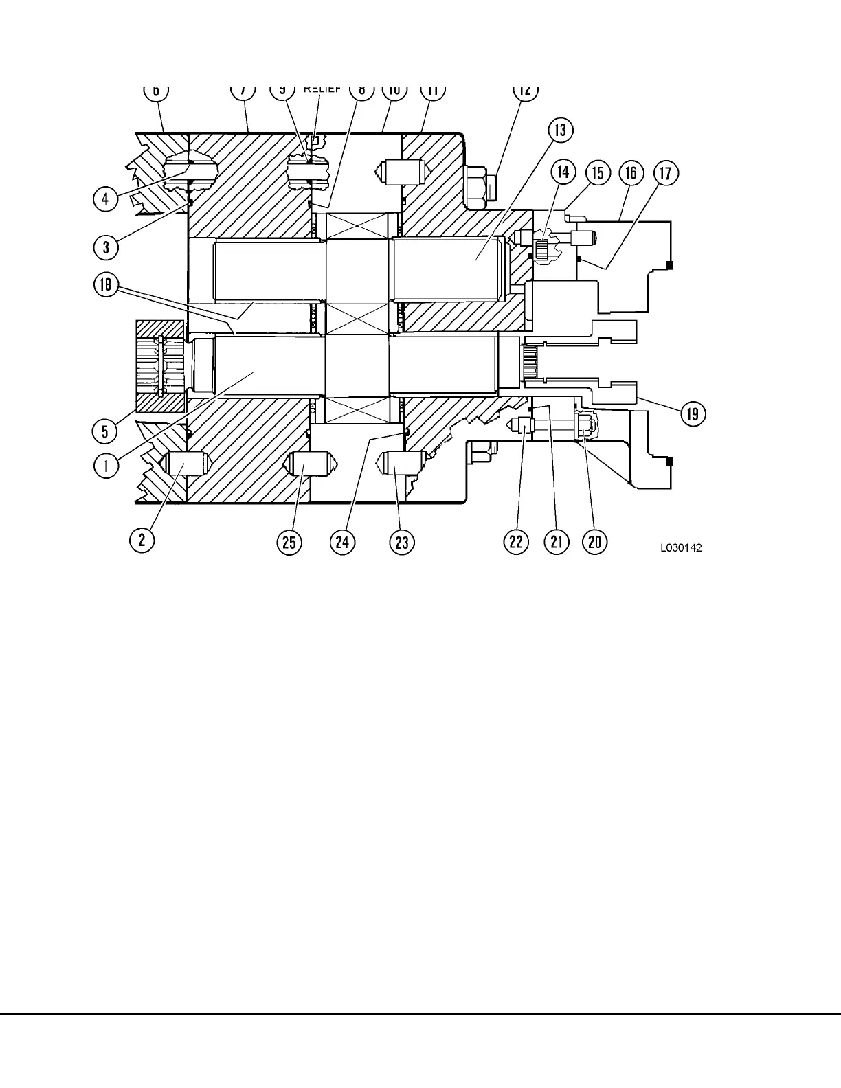
23. Lubricate and install O-ring (24, Figure 3-14) in
connector plate (11). Install dowel (23) if
removed. Lubricate I.D. of bearing in the con-
nector plate (11). Install connector plate (11)
with flat washers and nuts.
24. Install dowel (22) if removed. Lubricate and posi-
tion O-ring (17) in transition plate (16). Assem-
ble bearing plate (15) to transition plate and
install capscrews (14). Tighten capscrews to
standard torque.
25. Lubricate O-ring (21) and position on bearing
plate (15). Install the assembled bearing plate
and transition plate (15 & 16) to the connector
plate (11) and secure in place with nuts (20).
Tighten nuts to standard torque.
26. IInstall coupling (19).
27. Lubricate the thru stud threads and install two
opposite stud nuts and hardened washers.
Tighten nuts to 240 to 250 ft lbs (325 to 339
N.m) torque.
FIGURE 3-14. HOIST PUMP REASSEMBLY
1. Drive Gear (Rear)
2. Dowel
3. O-Ring
4. O-Ring
5. Coupling
6. Connector Plate
7. Bearing Plate
8. O-RIng
9. O-Ring
10. Gear Plate
11. Connector Plate
12. Stud
13. Idler Gear
14. Capscrew
15. Bearing Plate
16. Transition Plate
17. O-Ring
18. Bearings
19. Coupling
20. Nut
21. O-Ring
22. Dowel
23. Dowel
24. O-Ring
25. Dowel



 To Next Page