L03026 7/02 Hydraulic Component Repair L3-11
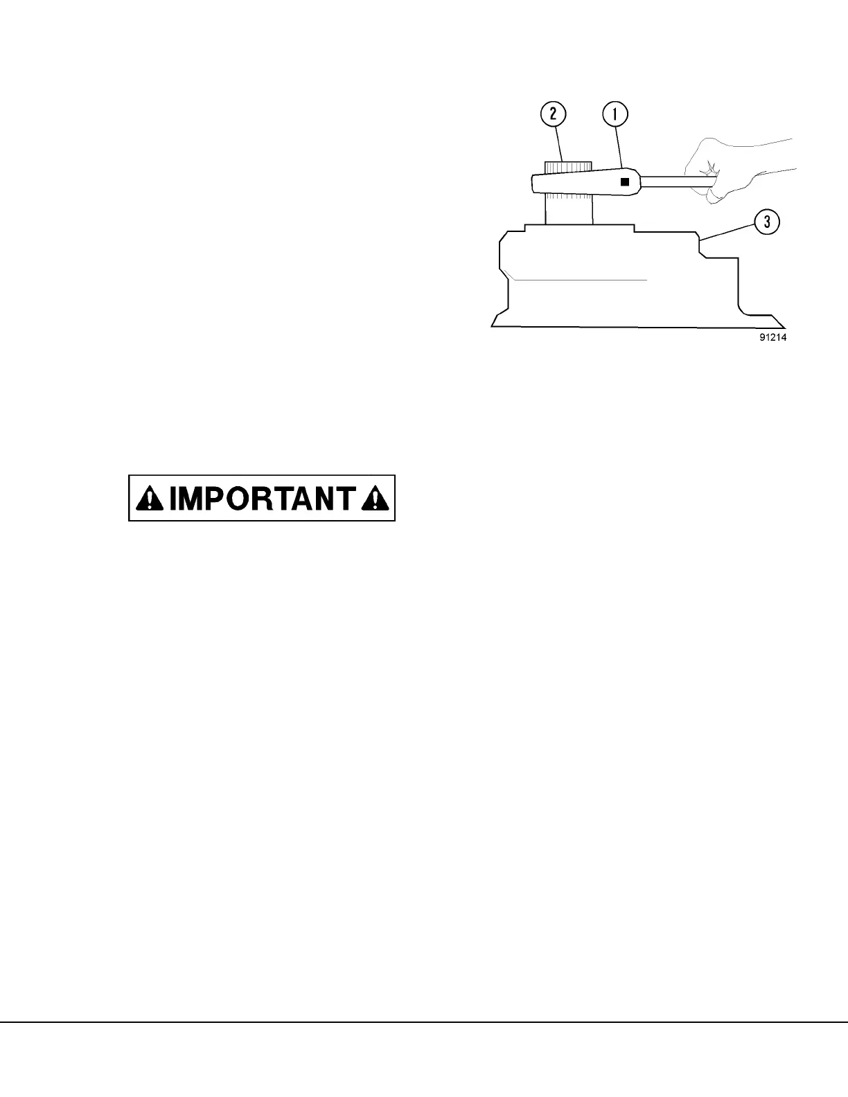
28. Using an 18 inch (45 cm) adjustable wrench,
check pump drive shaft rotation. The drive shaft
will be tight but should turn freely with a maxi-
mum of 5 to 10 ft lbs (7 to 14 N.m) torque, after
the initial surge. (Refer to Figure 3-15.)
29. If the shaft will not turn properly, disassemble the
pump and examine the parts for burrs or foreign
material causing buildup or interference
between parts.
30. When the input shaft turns properly install the
remaining hardened washers and nuts. Tighten
nuts to 240 to 250 ft lbs (325 to 339 N.m)
torque.
31. Install a new O-ring on steering pump flange and
install steering pump to the transition plate (16,
Figure 3-14). Install capscrews and tighten to
standard torque.
32. Install companion flange on pump driveshaft. If
necessary, heat to 400° to 500°F (204° to
260°C) to ease installation.
Do not force flange onto shaft. Be certain flange
is bottomed on shaft before it cools.
33. After flange has cooled, install nut and washer
on pump shaft. Tighten to 300 ft. lbs. (407 N.m)
torque.
FIGURE 3-15. PUMP ROTATION CHECK
1. Wrench
2. Input Shaft
3. Pump