L05026 Steering Component Repair L5-15
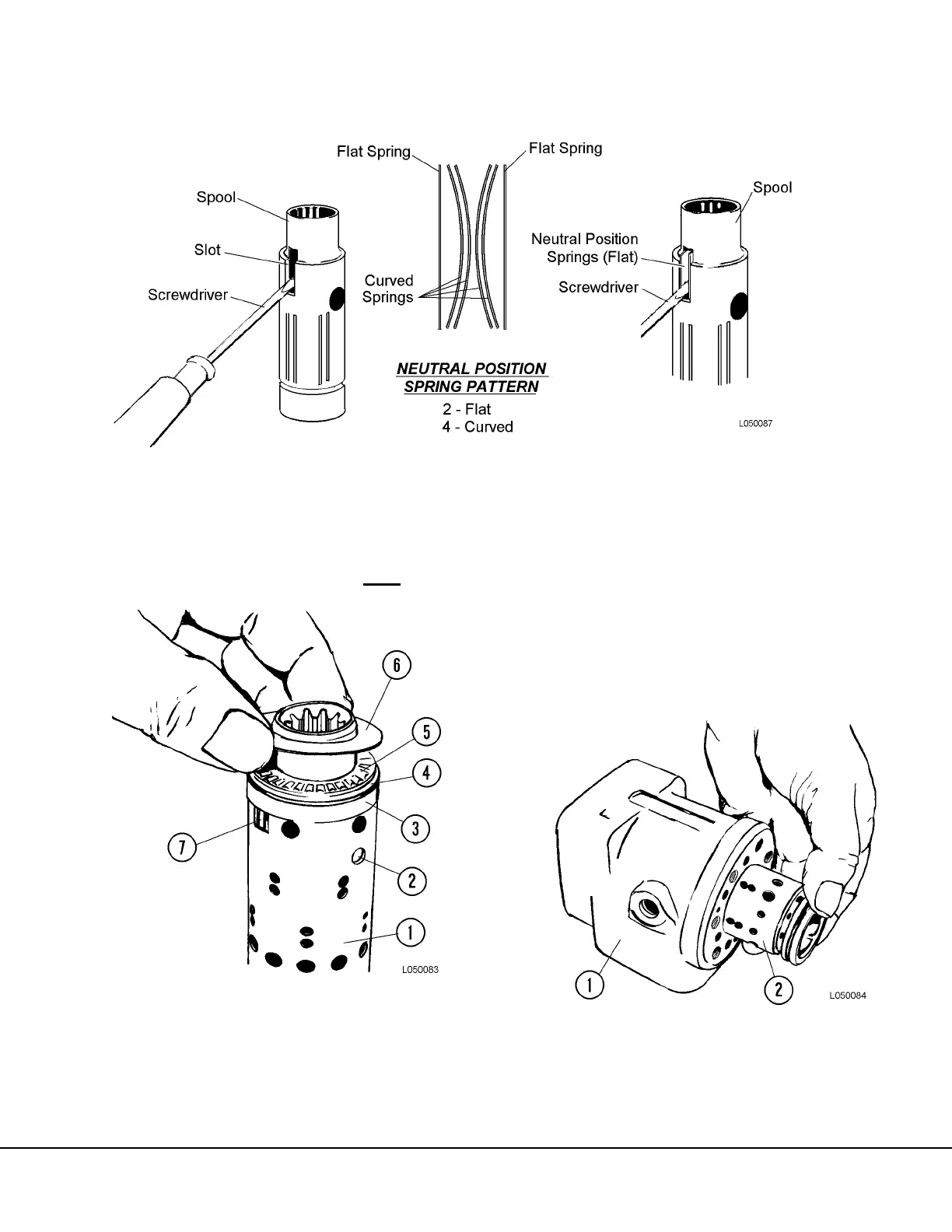
6. With neutral position springs (7, Figure 5-16)
centered in spool and sleeve, install ring (3),
rear bearing race (4), thrust bearing (5) and
front bearing race (6) in that order. The cham-
fer on the rear bearing race must
be facing
away from the bearing.
7. Place the dust seal (1, Figure 5-18) in position.
Using a flat iron block over the seal, tap into
position.
8. Position the O-ring and kin ring on the spool.
9. Position the steering unit with the housing hori-
zontal. Slowly guide the (lubricated) spool and
sleeve with fitted parts, into the bore using light
turning movements. Refer to Figure 5-17.
NOTE: Cross pin must remain horizontal when spool
and sleeve are pushed into bore to prevent pin from
dropping out of spool.
FIGURE 5-14. NEUTRAL POSITION SPRING INSTALLATION
FIGURE 5-15. BEARING INSTALLATION
1. Sleeve
2. Cross Pin
3. Ring
4. Bearing Race (with
chamfer)
5. Thrust Bearing
6. Bearing Race
7. Neutral Position
Springs
FIGURE 5-16. SPOOL INSTALLATION
1. Housing 2. Spool Assembly